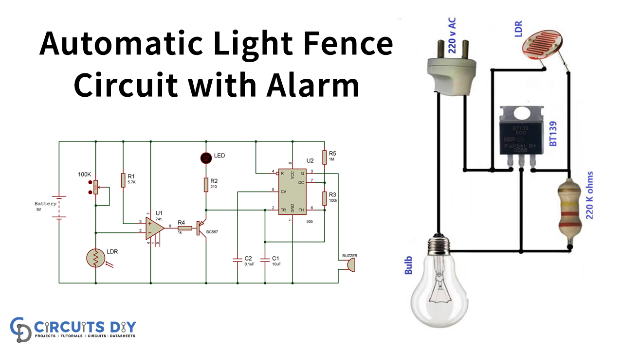
In this tutorial, we demonstrate a project of an “Automatic Light Fence Circuit with an Alarm.” We all have a question in our mind, that where we use these Light Fence Circuits. So, to recognize the presence of any human or element in a specific zone, a light fence circuit is used.
The distinguishing scope of the Light Fence Circuit is about 1.5 to 3 meters. It’s very easy to make the circuit utilizing LDR and Op-amp. This compact circuit can work easily with a regularly accessible 9V battery. The caution sound produced from the bell is sufficiently uproarious to recognize the presence of a car, element, or human.

Hardware Component
The following components are required to make an Automatic Light Fence Circuit
| S.no | Component | Value | Qty |
|---|---|---|---|
| 1. | Op-amp IC | LM741 | 1 |
| 2. | Transistor | BC557 | 1 |
| 3. | Potentiometer | 100 K | 1 |
| 4. | IC | NE555 timer | 1 |
| 5. | Resistor | 1K,5.7K,100K,1M,210 ohm | 1 |
| 6. | Capacitor | 0.1uF, 10uF | 1, 1 |
| 7. | Buzzer | – | 1 |
| 8. | LED | – | 1 |
| 9. | Battery | 9 V | 1 |
| 10. | Breadboard | – | 1 |
NE555 IC Pinout

For a detailed description of pinout, dimension features, and specifications download the datasheet of NE555 IC
LM741 Pinout
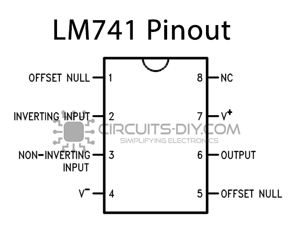
For a detailed description of pinout, dimension features, and specifications download the datasheet of LM741
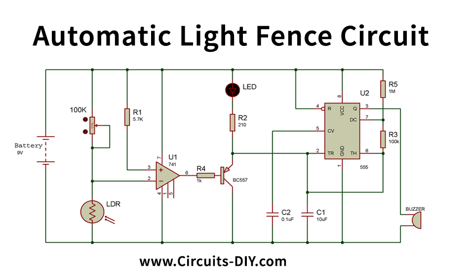
Automatic Light Fence Circuit
Working Explanation
This is the voltage comparator for the op-amp IC when the 555 timer IC is in an astable mode. The LDR and the potentiometer generate a voltage divider circuit. Based on the intensity of the LDR, the output of this divider circuit varies. The divider is attached to the op-amp IC inverting pin. A 5.7 K resistor connects the non-inverting pin, and thus the non-inverting voltage value is set. The voltage can be changed as needed by replacing this resistance with a 10 K potentiometer.
By using the serially attached VR1 potentiometer with the LDR, we can change the system sensitivity. When the non-inverting input’s voltage exceeds or is equal to the reference tension, the output (at pin 6) of the op-amp IC output is HIGH. Read more on how op-amp works through the different circuits on the op-amp basis.
As you can see in the schematic, the Op-amp IC goes low, and the PNP transistor T1 begins conducting when the LDR detects some operation. So the LED continues to shine with the IC of the 555 timers. In Astable mode, the 555 timer IC is provided, while R3, R5, and C1 have a preset delay.
So when someone or object comes into the forbidden place, the LDR detects his shadows and activates the warning.
Applications and Uses
Any element or person in a specific zone is to be identified using a light fence circuit.