In this tutorial, we are going to make a 555 one-shot timer. After one timing cycle is completed this circuit doesn’t repeat its timing cycle after we push switch S1 on or it remains pressed. You can also connect the output of any project to trigger the timer in the place of the push switch S1/ trigger switch. This circuit is working completely on the basis of a 555 timer IC.
It is used for different purposes such as a timer, delay, oscillator, or pulse generation. This IC is cheap and easily available therefore it’s commonly used in electronic circuits.
Hardware Components
The following components are required to make 555 Timer Circuit
| S.no | Component | Value | Quantity |
|---|---|---|---|
| 1. | DC Supply | 6-12V | 1 |
| 2. | IC | NE555 Timer | 1 |
| 3. | Switch | – | 1 |
| 4. | Relay | 6-12V | 1 |
| 5. | Diode | 1N4007 | 1 |
| 6. | Resistor | 270K, 560K | 2, 1 |
| 7. | Capacitor | 0.1µF, 10nF, 10µF | 1, 1, 1 |
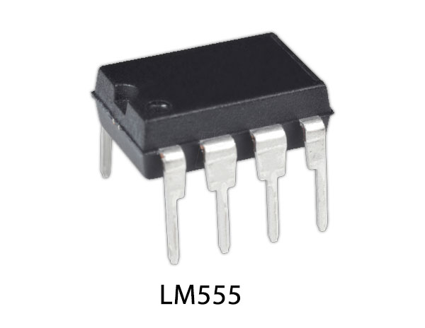
555 IC Pinout

For a detailed description of pinout, dimension features, and specifications download the datasheet of 555 Timer
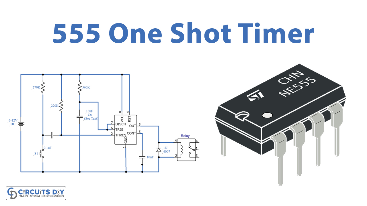
555 Timer Circuit

Working Explanation
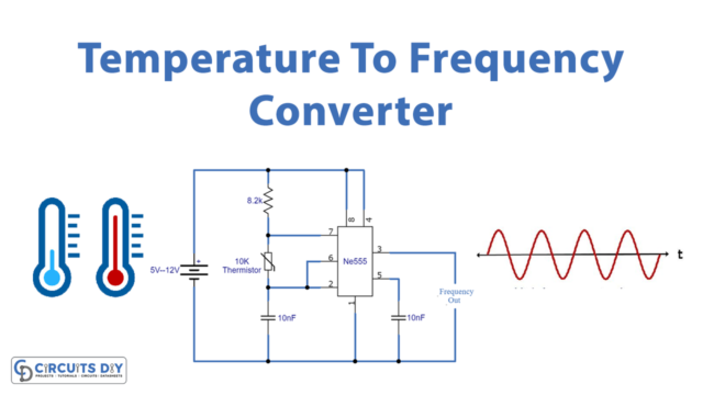
It is operating at 6 to 12 volts. The working is simple, 555 timer IC is providing a trigger signal after the switch S1 is pressed. This signal will activate the relay switch connected to the output of the IC. You can connect any AC or DC appliance to operate with this circuit. The time duration of this circuit depends on the value of the capacitor Cx as shown in the figure. We have used a 10µF capacitor which is providing a time duration of a few seconds. Increase its value to increase the time duration.
A 1000µF or 3000µF capacitor will increase the time duration to hours. the relay should have the same value as the operating voltage of the circuit, if the input supply is 6V then the relay should be 5-6V