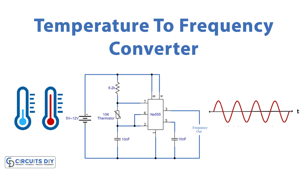
Here is a tutorial for a Simple 555 Temperature to Frequency Converter. The purpose of this circuit is to convert analog temperature signals to frequency signals. The conversion of these signals is a pretty common practice used in electronics applications. The circuit is simple and only uses a few components such as a 555 timer IC to provide oscillations, a thermistor to sense the temperature, some capacitors and resistors, and a battery.
The 555 timer IC has three modes of operation i.e. astable, bistable, and monostable multivibrator, it is connected as an astable multivibrator in this circuit. Since there are very few components, therefore, this circuit is inexpensive and easy to build.

Hardware Components
The following components are required to make Temp. To Frequency Converter Circuit
| S.no | Component | Value | Qty |
|---|---|---|---|
| 1. | Input Supply DC | 5-12V | 1 |
| 2. | IC | NE555 Timer | 1 |
| 3. | Thermistor | 10K | 1 |
| 4. | Resistor | 8.2KΩ | 1 |
| 5. | Ceramic Capacitor | 10nF | 2 |
NE555 IC Pinout

For a detailed description of pinout, dimension features, and specifications download the datasheet of 555 Timer
Temp. To Frequency Converter Circuit

Working Explanation
The operating voltage of this circuit is 5-12V DC. the temperature around the sensor is sensed by a 10K NTC thermistor and the output frequency of the 555 timer IC is directly proportional to the temperature sensed by it. So when the temperature increases the resistance of the thermistor is decreased and as a result, the output frequency of the 555 timer IC will increase. Similarly when the temperature decreases thermistor’s resistance increases and the output frequency of 555 timer IC will decrease. You can experiment with this circuit by changing the thermistor’s value along with the resistor.
Applications and Uses
- Modern temperature monitoring systems
- Weather monitoring systems
- Light sensors