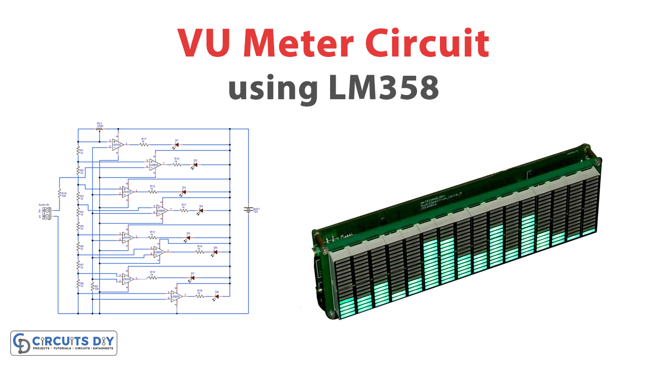
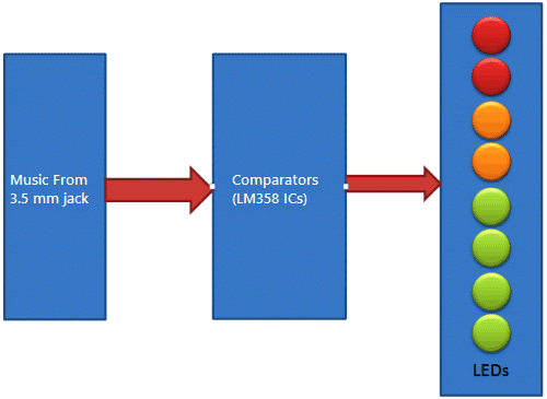
This article is about a simple VU meter using LM358 IC. A volume unit (VU) meter is a device that displays a representation of the signal level in audio equipment.
A volume unit or VU meter is a basic voltmeter that takes a simple average of the signal and displays it with a very small attack and releases time. VU meter responds in a fashion that is very similar to how human ears perceive loudness.
Hardware Components
The following components are required to make VU Meter Circuit
| S.No | Component | Value | Qty |
|---|---|---|---|
| 1. | Breadboard | – | 1 |
| 2. | DC Power Supply | 12V | 1 |
| 3. | Connecting wires | – | 1 |
| 4. | Op-Amp IC | LM358 | 4 |
| 5. | Variable Resistor | 100k | 1 |
| 6. | Resistors | 1k, 10k | 17, 1 |
| 7. | Audio Jack | 3.5mm | 1 |
| 8. | Aux Cable | – | 1 |
| 9. | LED | 5mm | 8 |
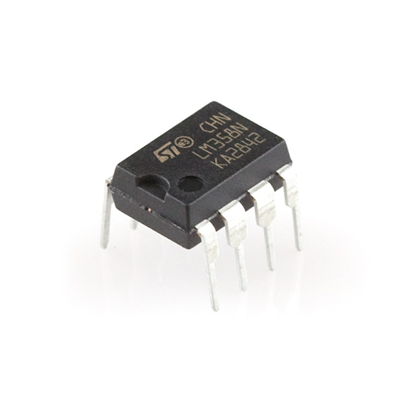
LM358 Pinout
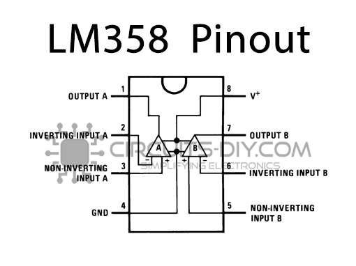
For a detailed description of pinout, dimension features, and specifications download the datasheet of LM358
VU Meter Circuit
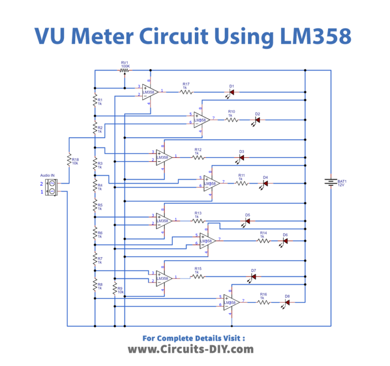
Working Explanation
A simple VU meter consists of a no. of LM358 dual op-amp ICs, each LM358 contains two comparators inside. These comparators compare the audio voltage signal with a reference voltage. In the VU meter, the reference voltage at the non-inverting terminal (+) is adjusted by the voltage divider circuit. It is built by using a pot and 1k resistors. 1k resistor is used at every comparator.
The advantage of the potentiometer (variable resistor) is that we do not have to change the values of all resistors for changing the reference voltage for each comparator. Instead, we can adjust it by only using the POT.
In VU meter circuit LEDs are connected in Reverse Logic. It means negative terminals of LEDs are connected to the output of the comparators. So, when the comparator output is high LED will be off, and when the output is Low the LED will be on.
Application
VU meters have usage where one has to observe the change in audio. It can show even the slightest change in the loudness of sound. They are mostly used in recording rooms and sound