Liquid-crystal displays come in various sizes and configurations, including their pinouts. Often, using these displays effectively requires access to the manufacturers’ documentation, which can be challenging to find when needed. Hence, having a small tester to identify the terminals becomes extremely useful.
A liquid-crystal display comprises two thin glass sheets with conductive tracks on their facing surfaces. These tracks are invisible when viewed straight on or at near-right angles but become visible at specific viewing angles.
Between these glass sheets is a liquid that changes its polarization when exposed to an electric voltage, affecting the light passing through. This polarization change creates light or dark segments, forming lines or shapes on the display. Testing a segment involves applying a low-voltage alternating current across it. It’s crucial to avoid using direct voltage, as it can irreversibly damage the display by removing the tracks due to the resulting current. Even a tiny direct voltage component in the alternating voltage should be avoided.
Additionally, an alternating current can partially remove tracks when flowing in one direction but restores them when flowing in the opposite direction.
Hardware Components
You’ll need the following hardware components to get started:
| S no | Components | Value | Qty |
|---|---|---|---|
| 1 | Integrated Circuit IC | CD4047 | 1 |
| 4 | Non-Polar Capacitors | C1=2.2nf | 1 |
| 5 | Resistors | R1=100K R2=10K R3=10K | 1 |
| 7 | Power Supply | 9V | 1 |
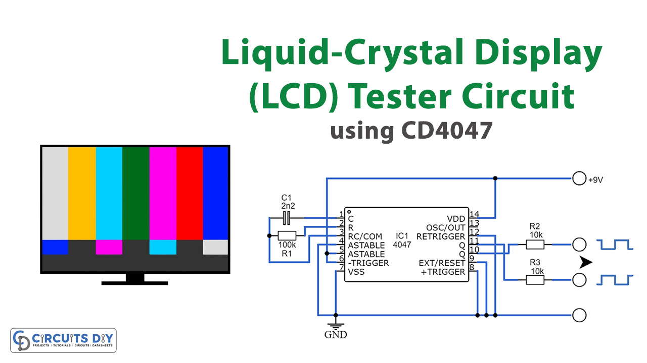
Schematic

The tester mentioned in this context features a square-wave generator that produces a perfectly symmetrical alternating voltage without any direct current (d.c.) component. Unlike most logic oscillators that generate rectangular waveforms with a duty cycle close to 50%, the 4047 chip used in this tester ensures symmetry through a binary scaler in its output. The oscillator’s frequency operates at around 1 kHz and can be powered from a 3–9 V source, typically a battery, although a variable power supply offers certain advantages. For instance, it helps determine the voltage range within which the display functions optimally and reveals the relationship between voltage levels and the display’s legibility at various angles.
The tester’s current draw remains below 1 mA. It’s crucial to always connect the test voltage between the common terminal (the backplane) and one of the segments. If unsure about which terminal serves as the backplane, connect one probe of the tester to a segment and then test each of the other terminals until the segment becomes visible. However, note that some LCDs may have more than one backplane. Therefore, if a segment remains invisible, investigate whether the display incorporates a second backplane terminal.