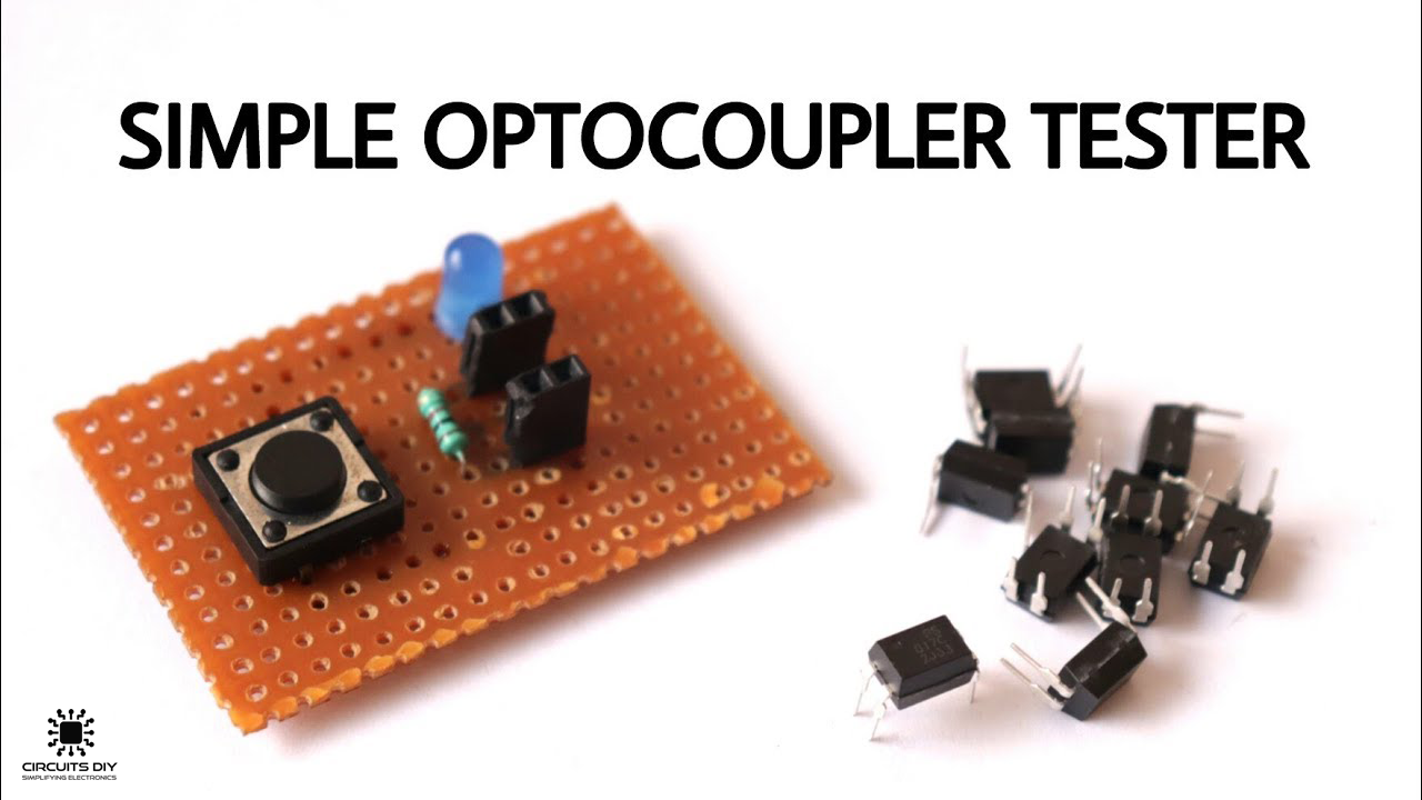
What is an Optocoupler Tester?
An optocoupler is a simple electronic component that is used to connect separate circuits together by the means of a light sensitive optical interface. An optocoupler or optoisolator consists of a light emitter, the IR LED, and a light-sensitive receiver which can be a single photo-diode, photo-transistor, photo-resistor, photo-SCR, or a photo-TRIAC. Optocoupler testers are used to check the functionality of any optocoupler receiver. It is a simple, useful & inexpensive circuit that helps you in determining the functional health of an optocoupler. So, in this tutorial. we are going to go over a step by step process on How To Make an Optocoupler Tester Circuit for the PC817 general purpose optocoupler.
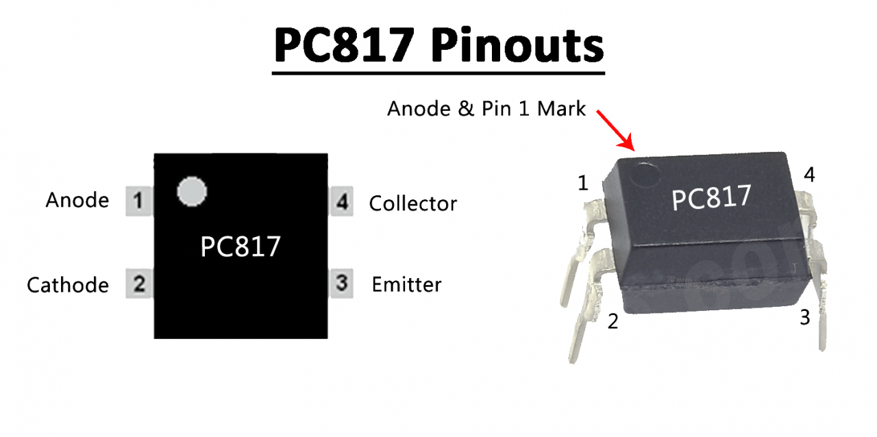
PC817 IC contains an IR LED optically coupled to a phototransistor. It is packaged in a 4 pin DIP, available in wide-lead spacing option and SMT gullwing lead-form option. Basically, this IC packaging consists of an IR LED & and a photo-transistor inside of it. When the IC is powered, The rays from the IR LED fall on the base of the phototransistor & allows it to conduct.
JLCPCB is the foremost PCB prototype & manufacturing company in china, providing us with the best service we have ever experienced regarding (Quality, Price Service & Time).
Hardware Components
You will need the following parts to build this project.
| S.no | Component | Value | Qty |
|---|---|---|---|
| 1 | Optocoupler IC | PC817 | 1 |
| 2 | LED | 5mm, 3.5V | 1 |
| 3 | Button | – | 1 |
| 4 | Resistor | 1K | 1 |
| 5 | Female Headers | – | 4 |
| 6 | Soldering Iron | 45W – 65W | 1 |
| 7 | Soldering Wire with Flux | – | 1 |
| 8 | Veroboard | – | 1 |
| 9 | DC Battery | 9V | 1 |
| 10 | Battery Clip | – | 1 |
| 11 | Jumper wires | – | As per need |
PC817 Optocoupler Pinout
Useful Steps
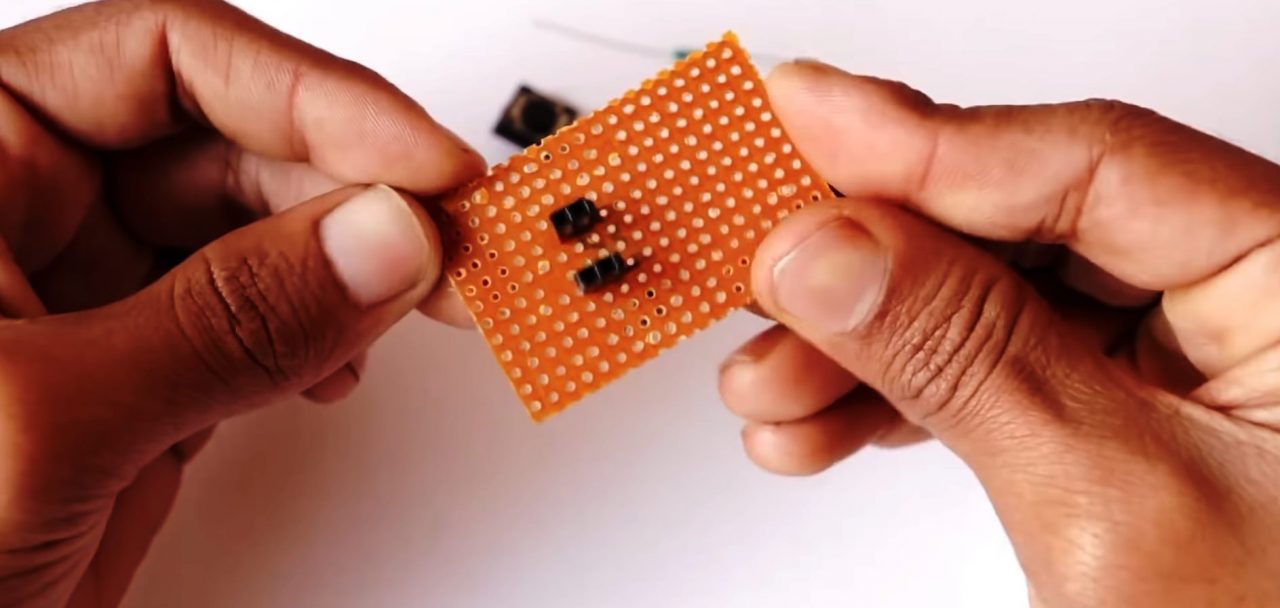
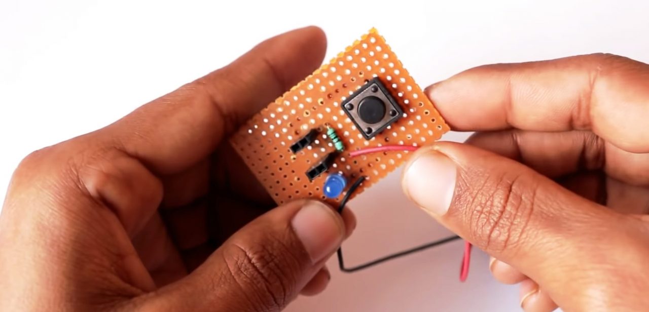
1) Solder two pairs of 2 female headers on the veroboard.
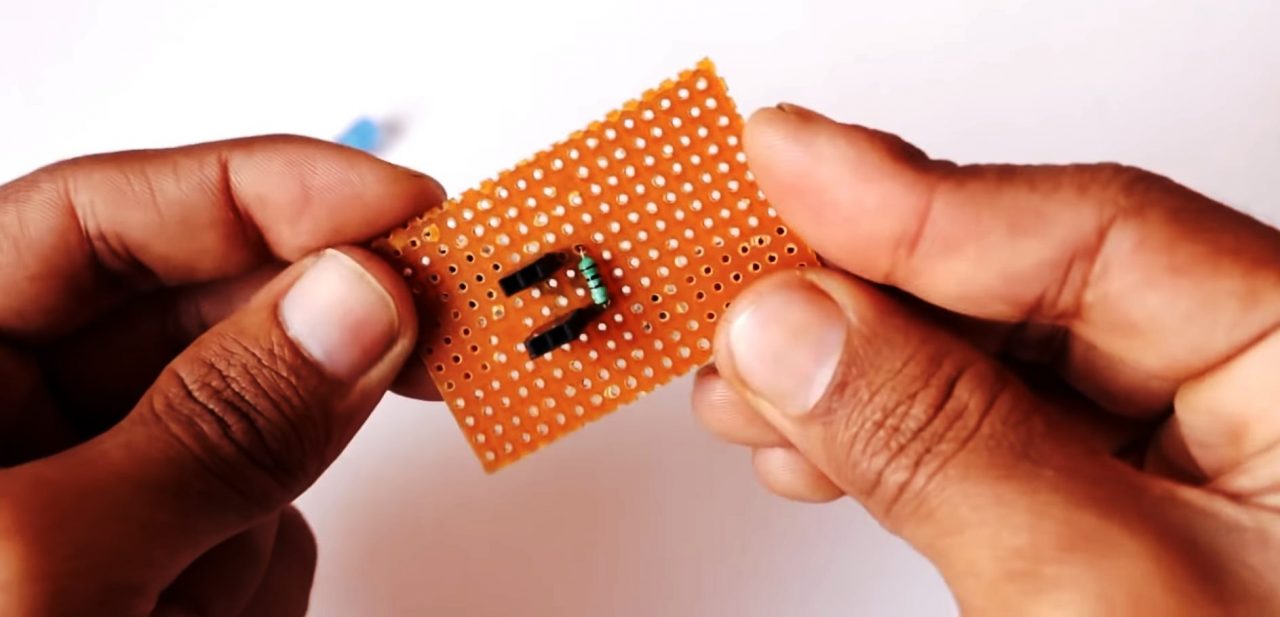
2) Connect a 1K resistance in series between the two female header pairs.
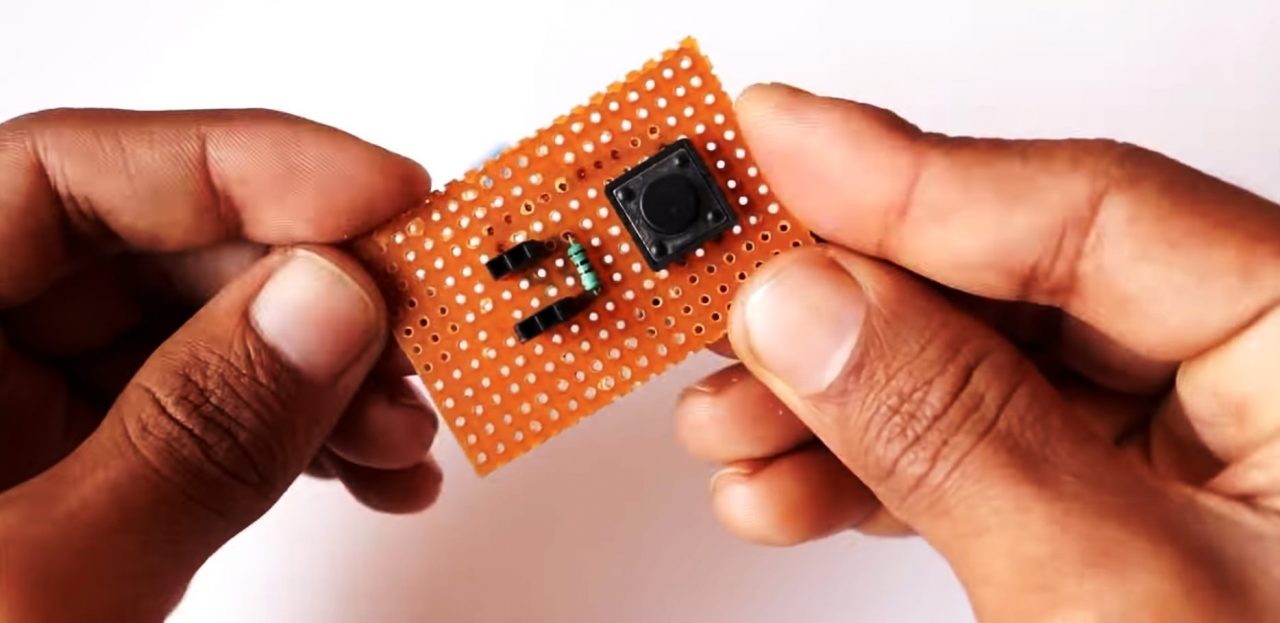
3) Solder the Pushbutton in series with the female headers.
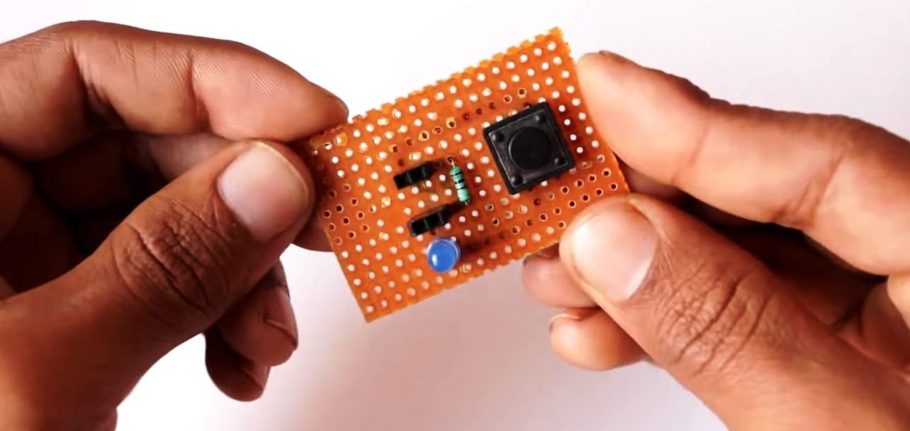
4) Solder the +ve terminal of the LED with output female header & the -ve terminal with the ground of the circuit.
5) Connect the 4V DC battery with the circuit.
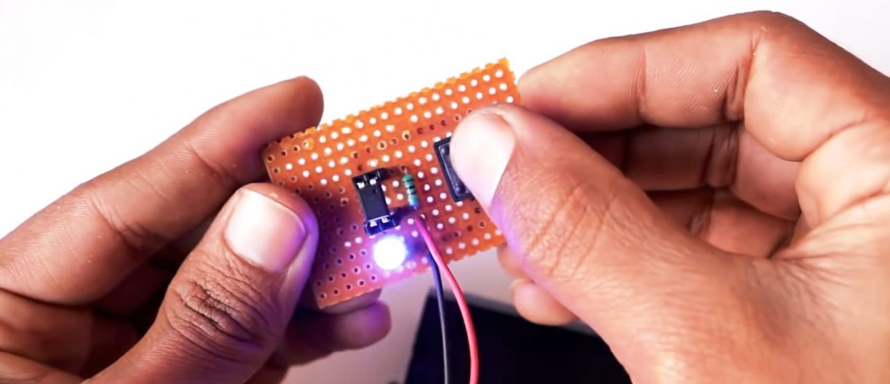
6) Place the optocoupler IC in the female headers. Power up & test the circuit.
Circuit Diagram For Optocoupler Tester
Working Explanation
This circuit is basically used to perform the functionality test of any 4-pin optocoupler IC. In order to perform the functionality test, place the IC in the female headers so that the emitter of the phototransistor & IR LED anode pins of the IC are connected to the GND of the circuit, while the IR LED cathode & phototransistor collector pin of the IC is connected to the 4V VCC.
Now, Connect the circuit to power. On pressing the push button if the LED glows connected to the emitter terminal glows, it means that the optocoupler IC is functioning normally. If the LED doesn’t glow, it means that the IC needs to be replaced.
Applications
- This circuit can be used to perform functional testing of any 4-Pin optocoupler IC.