In several sectors of the construction industry, airflow monitoring is useful. In this tutorial, we create a very straightforward circuit for the existence of an airflow “simple air flow detector circuit.” No sophisticated stuff such as Resistance Temperature Detector (RTD) or the Zener diode is necessary for this circuit.
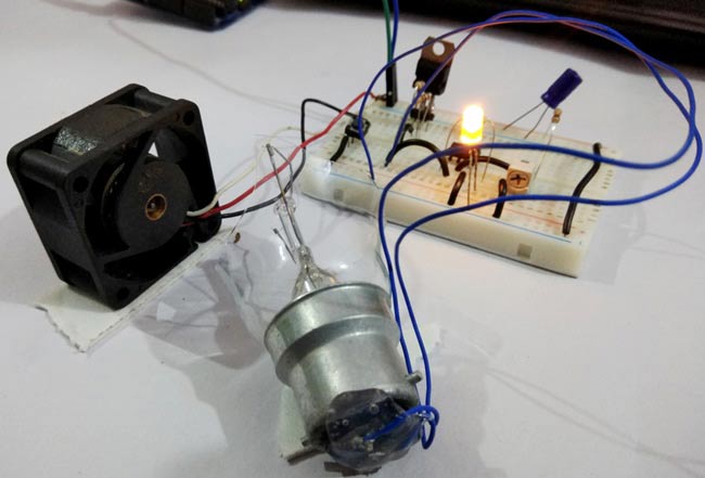
We use a simple AC bulb fluorescent with some cheap air detecting parts. This project with significantly smaller components is inspiring, and it is easy to use all the materials for this design.
Hardware Component
The following components are required to make Air Flow Detector Circuit
| S.no | Component | Value | Qty |
|---|---|---|---|
| 1. | Bread Board | – | 1 |
| 2. | Jumper wire | – | – |
| 3. | Power Supply | 12v | 1 |
| 4. | Capacitor | 100uF | 1 |
| 5. | Incandescent Bulb | – | 1 |
| 6. | LED | – | 1 |
| 7. | Push-button (Optional) | – | 1 |
| 8. | Resistor | 10K, 100 Ohm, 330 Ohm, 680 Ohm, 50K Var | 1, 1, 1, 1, 1 |
| 9. | DC Fan (Optional) | – | 1 |
| 10. | Voltage Regulator | LM7805 | 1 |
| 11. | Dual Op-Amp IC | LM358 | 1 |
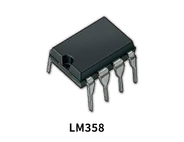
LM358 Pinout

For a detailed description of pinout, dimension features, and specifications download the datasheet of LM358
LM7805 Pinout

For a detailed description of pinout, dimension features, and specifications download the datasheet of LM7805
Air Flow Detector Circuit
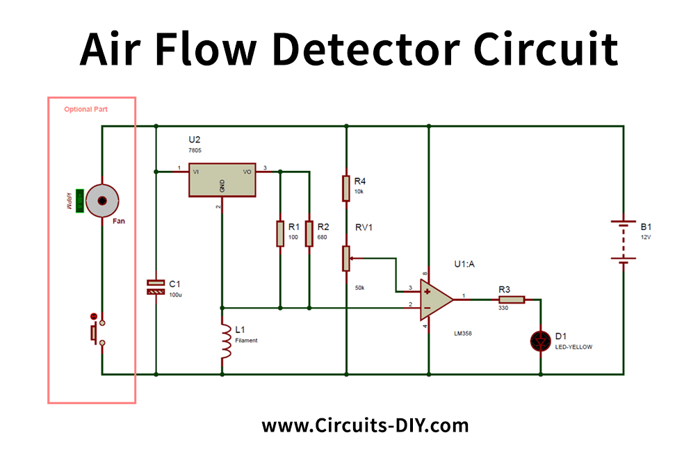
Circuit Operation
This circuit is a tactile airflow warning. This circuit helps us to detect air presence or wind speed. This ventilation sensor circuit consists mainly of the bulb filament, causing voltage variation when the air circulation is in location. The Bulb filament has a coefficient of sense of danger, and its filament resistance varies in reverse to the altitude. Filament resistance will be minimal, and conversely when the temperature is high.
So if there is no air by design, the bulb filament’s resistance value is low because of some wind. The bulb filament’s humidity or wind speed decreases, and the filament intensity improves, like any airflow enters. And because of this capacitance. So, the bulb filament produces a signal gap. The Op-amp LM358 detects this voltage difference and has a low signal. Op-amp is programmed in emitter mode that contrasts the input’s amplitude to the reference voltage and therefore provides the output. See more LM358 and op-amp circuits here.
For circuit calibration, a potentiometer is being used. The ventilation is indicated by an LED. To wind through the filament, a pushbutton and a DC fan are being used. The consumer can flow air through his mouth, though, too. This entire circuit is supplied with 12v DC.
Applications and Uses
This circuit is being used to detect ventilation in areas such as the car motor, where the fuel consumption of the engine has to be analyzed. This circuit can also be used as an atmospheric pressure detector as well including an exhaust gas detector.