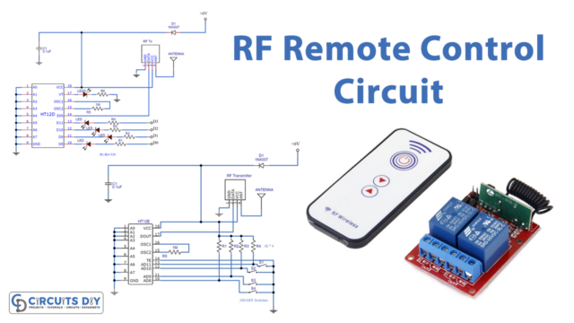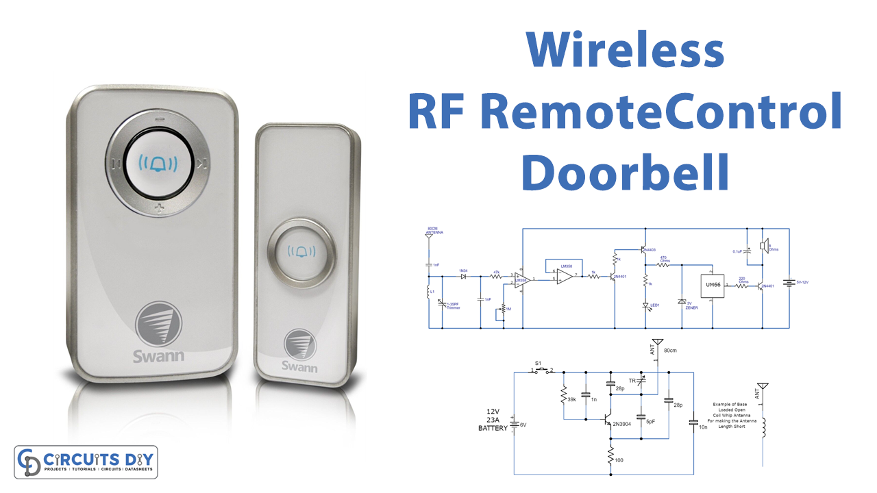
In this DIY, we are going to demonstrate a Wireless RF Remote Control Doorbell Circuit. Remote RF doorbells or remote control doorbells are common these days, they can also be utilized as remote calling bells. Each RF wireless bell is comprised of two sections which are an RF transmitter/remote control and a receiver with a melody or alarm generator. You can also buy wireless bells in stores but making them at home will spare you a great deal of cash and furthermore show you the working idea of these bells.
Hardware Components
The following components are required to make a Wireless RF Receiver Circuit
| S.no | Components | Value | Qty |
|---|---|---|---|
| 1 | IC | LM358 | 2 |
| 2 | Battery | 5 – 12V | |
| 3 | Melody generator IC | UM66 | 1 |
| 4 | Zener Diode | 3V | 1 |
| 5 | Antenna | 80cm | 1 |
| 6 | Transistor | 2N4401, 2N4403 | 2, 1 |
| 7 | Capacitors | 0.1µF, 1nF | 1, 1 |
| 8 | Coil | 6 turns | 1 |
| 9 | Speaker | 8Ω | 1 |
| 10 | LED | – | 1 |
| 11 | Variable Capacitor | 1-35pF | 1 |
| 12 | Resistor | 1MR, 47KR, 220Ω, 470Ω, 1K | 1, 1, 1, 1, 2 |
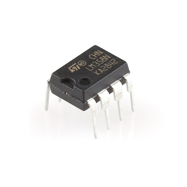
LM358 Pinout
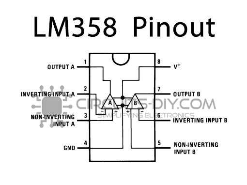
For a detailed description of pinout, dimension features, and specifications download the datasheet of LM358
Receiver Circuit

Hardware Components
The following components are required to make Wireless RF Transmitter Circuit
| S.no | Components | Value | Qty |
|---|---|---|---|
| 1 | Transistor | 2N3904 | 1 |
| 2 | Antenna | 80cm | 1 |
| 3 | Coil | 2 turns | 1 |
| 4 | Variable Capacitor | 1 – 35pF | 1 |
| 5 | Resistor | 39K, 100Ω | 1 |
| 6 | Ceramic Capacitor | 1nF, 28pF, 5pF, 62pF, 10nF | 1 |
| 7 | Switch | – | 1 |
| 8 | Battery | 12V 23A | 1 |
2n3904 Pinout
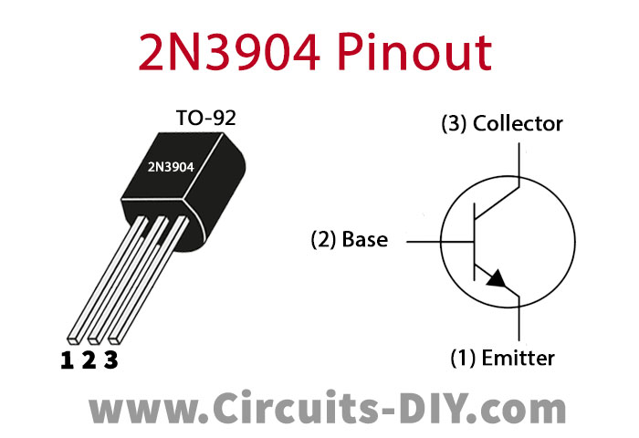
For a detailed description of pinout, dimension features, and specifications download the datasheet of 2n3904
RF Transmitter Circuit
Circuit Operation
The circuit of the wireless bell is very simple to fabricate and utilizes just a couple of low-cost segments. A UM66 melody generator is associated with the yield of the receiver circuit which will be initiated when the receiver circuit gets signals from the transmitter.
The Receiver circuit is really an RF detector circuit, which detects the RF signals produced from the transmitter, and amplifies them. An LC circuit with a germanium diode indicator circuit is utilized at the front finish of the circuit to identify the signals from the transmitter. The germanium diode value isn’t basic and you can utilize any similar germanium diode. The 1 – 35pF variable capacitor is utilized here to adjust the receiver with the transmitter.
Another part of the circuit is a transmitter circuit. The transmitter circuit is really a basic FM transmitter circuit. In this circuit, L1 is likewise air-cored and equivalents to two turns of #24 enameled wire coiled on a 5mm structure. The TR is the equivalent on both receiver and transmitter for example 1 to 35 pF variable capacitor. The antenna length of the two sections for example receiver and transmitter is 80cm.
The working voltage of the circuit is 12V DC. A little 12V 23A size battery will be perfect to use with the circuit.
Applications and Uses
The Wireless RF Remote Control Doorbell is used as a wireless doorbell where you don’t want any cables and is also used as security doorbell.