
Introduction
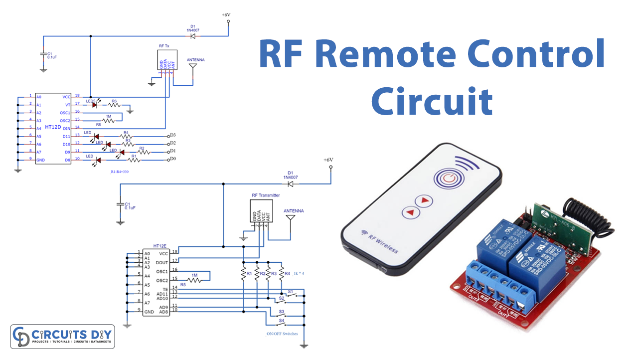
In this tutorial, we are going to make an “RF remote control circuit.” RF Remote Control is ideal for usage in short-range RF remote control products. The compact but effective circuit may easily and conveniently manage the majority of relevant wireless systems, including alarm systems, garage door operations, light controls, or other remote control appliances.
This circuit is made from easily available components. Also, b This remote provides roughly 150 meters of coverage, which may be expanded to 200 meters by expanding the ariel cable.
Hardware Required
| S.no | Component | Value | Qty |
|---|---|---|---|
| 1. | IC | HT12D | 1 |
| 2. | RF Tx | – | 1 |
| 3. | Diode | 1N4007 | 1 |
| 4. | Antenna | 1 | |
| 5. | Capacitor | 0.1uF | 1 |
| 6. | Register | 1K, 1MΩ | 4, 1 |
| 7. | Switches | – | 4 |
Circuit Diagram
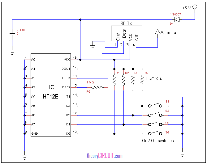
Transmitter Circuit Diagram
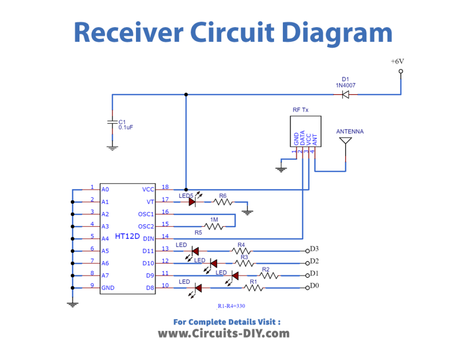
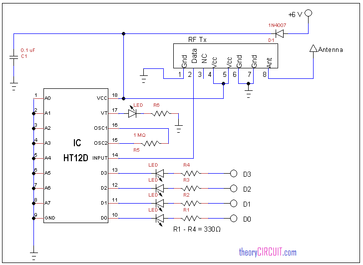
Receiver Circuit Diagram
Working Explanation
This RF Remote Control Circuit certainly has two circuits:
- A transmitter circuit
- A receiver circuit
Transmitter Circuit
There are three stages in this circuit.
- Input switch: The data pin of the encoder IC is connected to the input switches. By turning on any switch and connecting the data input pin of the encoder IC to the ground, these switches determine whether it is on or off.
- Encoder IC HT12E: The encoder IC contains an internal oscillator. Address lines A0 to A7 of the encoder are connected to the ground which is usually used for encoding address data with a unique identity; however, these pins are not required for this project.
- RF transmitter;434 MHz ASK module: ASK transmitter chip converts the encoded data from IC HT12E into an RF signal, which is then sent into the air using a regular wire for short distances, and an antenna or ariel for longer distances. Output Dout pin 17 is wired to the data pin of the RF transmitter.
Receiver Circuit
The three stages in this receiver circuit are:
- RF Reciever;434 MHz ASK module:: The ASK Transmitter Module transmits an RF signal, which is received by the RF receiver, which then outputs through pin 2.
- IC decoder HT12D: The signal is sent into the decoder IC HT12D’s input pin 14, where the Address pins A0 to A7 are terminated to the ground just like they are in the encoder IC. This ensures that the address in the transmitter and reception circuits are identical.
- Output data line: The decoder IC gives data output from D3 to D0 pins, which correspond to the switch situations in the transmitter circuit.
Application and Uses
- Televisions
- Audio sound control
- Lightning control, etc


