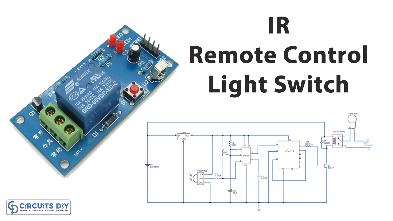
In this tutorial, we are going to make an “IR Remote Control Light Switch”.
Have you ever wanted to turn off the lights without moving, especially when you started a film on TV or when you fell asleep after a busy day? If the switch is out of reach, it is most likely to leave the lights on. For this, we built the perfect solution; an IR remote-controlled light switch. We can use any IR remote control to turn ON or OFF home appliances by using IR remote control light switch circuit. In this circuit, we used an IR receiver, TSOP 1738 (you can use TSOP 1736 also) these sensors are capable of receiving 36 kHz to 38 kHz IR signals from any Remote control.
Hardware Required
| S.no | Component | Value | Qty |
|---|---|---|---|
| 1. | IR Receiver | TSOP1738 | 1 |
| 2. | Regulator IC | 7805 | 1 |
| 3. | Timer IC | LM555 | 1 |
| 4. | Decade Counter Divider IC | CD4017 | 1 |
| 5. | NPN Transistor | BC547 | 1 |
| 6. | Relay | 9V | 1 |
| 7. | Diode | 1N4007 | 1 |
| 8. | Resistor | 100KΩ, 330Ω | 2, 1 |
| 9. | Capacitor | 0.01μF, 10μF | 2, 1 |
| 10. | Connecting Wires | – | – |
| 11. | Battery | 9V | 1 |
Circuit Diagram
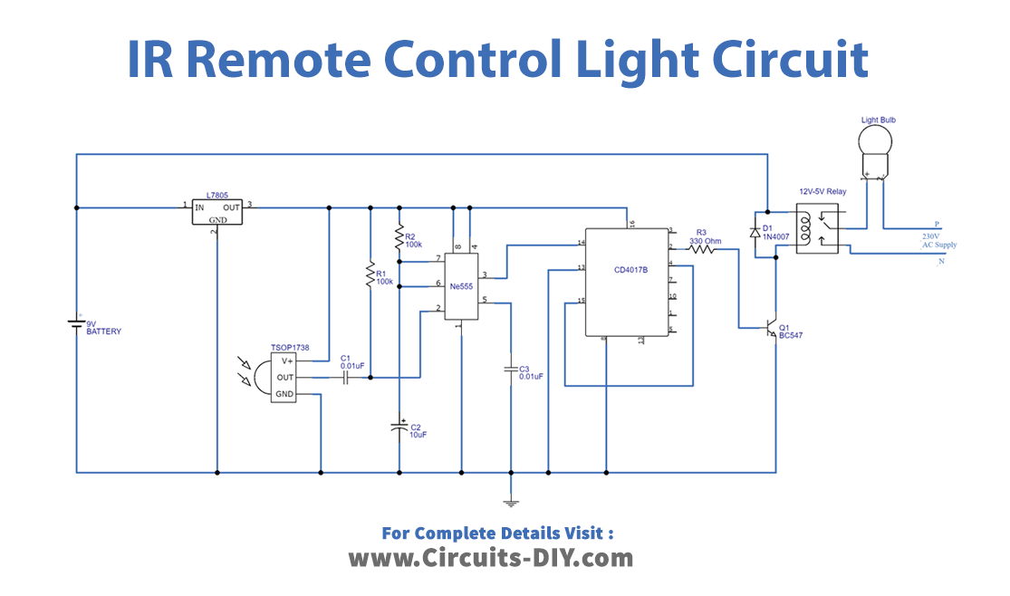
Working Explanation
This circuit makes turn ON and turn OFF electrical appliances by receiving any IR (Infra-Red) signals from the remote control. Here as a target, we took an electrical bulb and connected it to the relay between the common and Normally Open (N/O) terminals of the relay, and this relay gets energized from a 9 Volt battery. Now as we can see in the circuit first LM7805 regulator IC is used to provide a regulated 5V DC supply to the IR sensor, timer, and counter IC. TSOP 1738 sensor output is connected with the timer IC trigger Pin, it produces output and triggers the timer IC when the IR signal is received by TSOP 1738 sensor. Here timer IC produces a single pulse as it is configured in a monostable multivibrator. Single-pulse depends on the timer Resistor (R2) and Capacitor (C2) value. Output from the timer is applied to the clock input of IC 4017 (Decade Counter IC 4017 Holds output Strongly also noise Resistant) this IC counts the clock, If the count starts from zero then Q1 output becomes HIGH then transistor BC 547 gets turned on and makes the relay to get ground supply, then Relay coil gets energized and attracts the lever to N/O contact then the bulb gets power supply and starts to glow. If the counter IC gets pulse from timer IC and the counter starts the count from one (Q1 – HIGH) then Q1 output becomes LOW and this signal is biased to reset pin 15 and hence everything on the counter gets reset. Hence the Q1 becomes low or zero means the transistor turns OFF, so the relay also gets turned OFF. Here the bulb is disconnected from the AC supply and turned OFF.
So, the output from the IR sensor is taken to the timer circuit and counter stage then Relay to control the light bulb or any other electrical appliances.
Applications
- Can be used to remotely control home appliances (Fridge, TV, Fan, etc.)
- Wireless controlling
- IR doorbells & security alarms