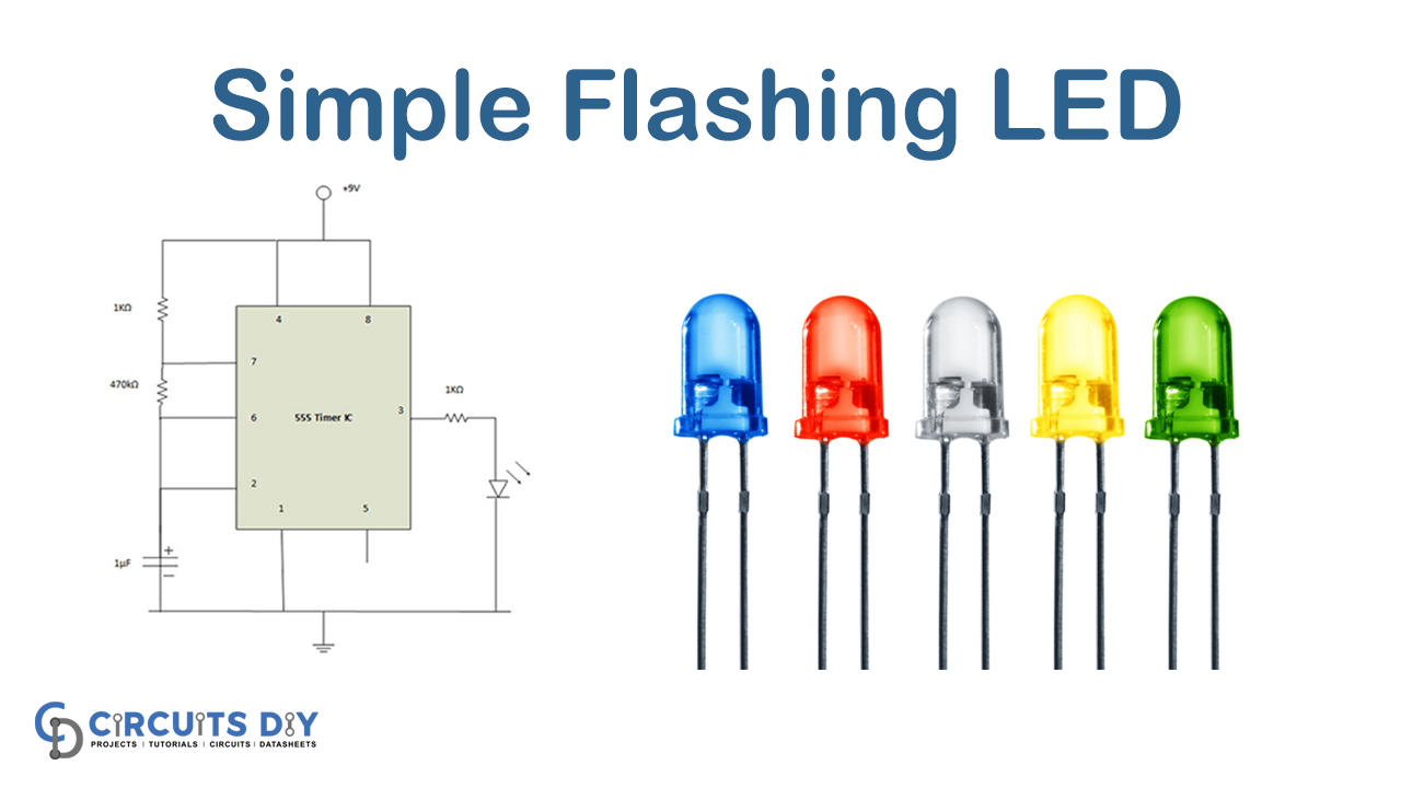
In this DIY, we are demonstrating the project of a Simple Flashing LED. This project is easy to manufacture and requires a few components. You want to create simple circuits such as LED circuits to get to know basic circuit design principles when you begin with electronics.
For you, here’s a circuit of 555 timer IC– an LED flash circuit diagram. The tutorial will teach you how to illuminate and dim at a specific time with some readily available electronic components and a diagram that is easy to understand. Here’s the step-by-step pattern for this LED circuit.
Hardware Components
The following components are required to make Flashing LED Circuit
| S.no | Component | Value | Qty |
|---|---|---|---|
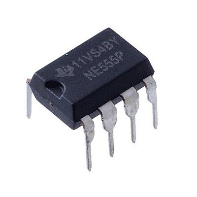
| 1. | IC | NE555 timer | 1 |
| 2. | Electrolytic Capacitor | 1uF | 1 |
| 3. | Battery | 9V | 1 |
| 4. | Resistor | 470K, 1K | 1, 2 |
555 IC Pinout

For a detailed description of pinout, dimension features, and specifications download the datasheet of 555 Timer
Flashing LED Circuit

Working Explanation
The battery can be blinking the LED until you connect it to the circuit. Check the association again if it doesn’t work. Assure that the battery is correctly attached to the breadboard and that electricity enters the circuit components.
The LED flashing rate can be adjusted here with a different capacitance to adjust capacitance. If you want to add additional LEDs to this blinking LED circuit, use appropriate resistors to connect them to the first LED.
Applications and Uses
The dancing LED circuit can also be used on roads for any visual sign indications or promotional hoarding.