Introduction
To ensure the various process in different industries, the temperature is an important physical measurement. As you know that industries have furnaces, freezing substances, melting machines, therefore in industries and the industrial process, temperature indicators play a vital role. Usually, they are used to determine the temperature readings or levels. Moreover, it prevents the machines and environment from any hazardous or physical harm. Several temperature sensors and indicators are available in the market. We are using a sensor that uses few components. So, in this tutorial, we are going to ” LM35 Temperature Indicator LED circuit “
Hardware Required
| S.no | Component | Value | Qty |
|---|---|---|---|
| 1. | Temperature Sensor | LM35 | 1 |
| 2. | Operational Amplifier IC | MC1458 | 1 |
| 3. | NPN Transistor | BC547 | 2 |
| 4. | Potentiometer | 10KΩ | 1 |
| 5. | LED | – | 2 |
| 6. | Resistor | 8.2KΩ, 10KΩ, 680Ω | 2 ,1, 3 |
| 7. | DC Supply | 5V | 1 |
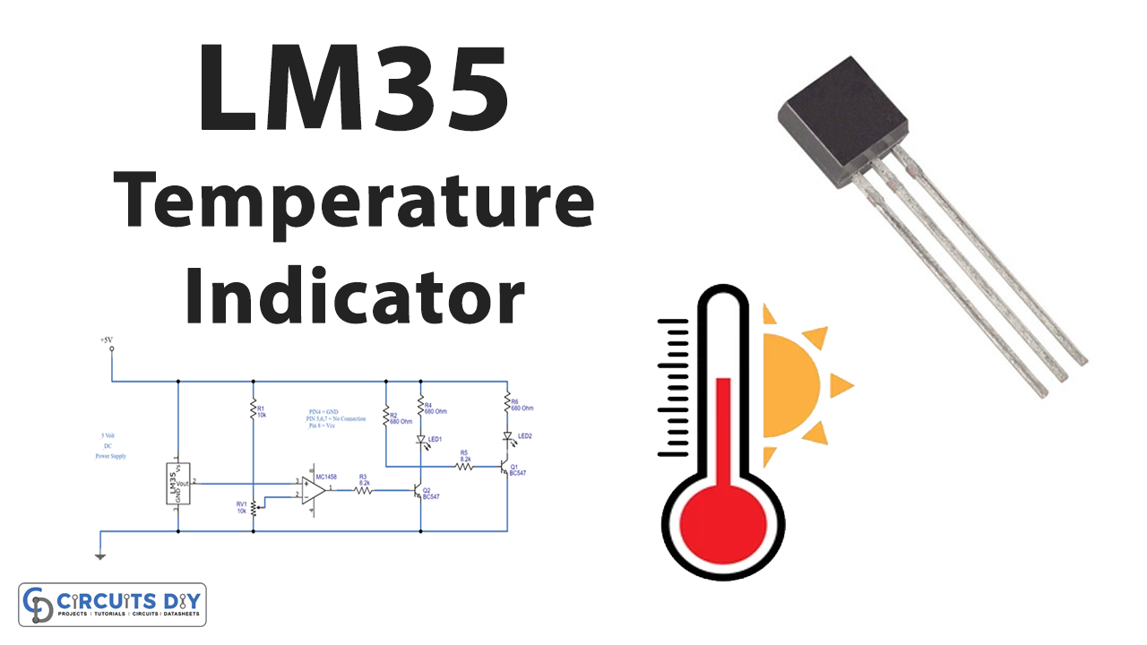
Circuit Diagram

Working Explanation
In this circuit of LM35 Temperature Indicator LED, the output of LM35 is given to MC1458 which are working as an operational amplifier. The output of this MC1458 is given to the base of the transistor Q1 with the help of Resistor R3. The output of transistor Q1 is taken at the collector which is connected with the base of the transistor Q2 through resistor R5. Red LED is wired as the output of Q1 and Green LED is connected as the output of transistor Q2.
If the temperature is below the threshold level, MC1458 doesn’t create any output, ao the Q1 transistor remains OFF. In this case, transistor 2 gets supply and the green LED turns ON. When the temperature goes above the threshold level, MC1458 produces output and turns ON the transistor Q1. This makes the Red LED glow while green remains OFF.
Application and Uses
- The circuit is used in industris to detemine the temperature level of different industrial machines and equipments.