Today we are going to give you a description of a Light Activated Alarm circuit by using 555 timer IC in detail. Meanwhile, this light enacted alarm circuit along with the 555 timer IC utilizes a light detective resistor or LDR to frame a light-sensitive intruder alarm framework. However, it is likewise used for turning on a light at Sunset and off at Sunrise.
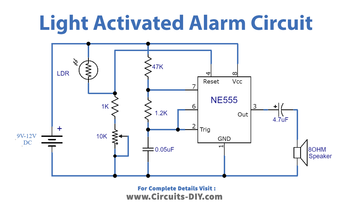
The circuit diagram underneath shows the venture of a light-activated alarm circuit utilizing a 555 timer IC. However, the circuit will create sound when light falls on the surface of the LDR. Furthermore, the core of the circuit is a renowned 555 timer IC that wires as an Astable Multivibrator in the circuit. An LDR (Light Dependent Resistor) utilizes here as a light sensor.

Hardware Components
The following components are required to make Light Activated Alarm Circuit
| S.no | Component | Value | Qty |
|---|---|---|---|
| 1. | IC | NE555 Timer | 1 |
| 2. | LDR | – | 1 |
| 3. | Speaker | 8 ohms | 1 |
| 4. | Resistor | 1K, 1.2K, 47K | 1, 1, 1 |
| 5. | Potentiometer | 10K | 1 |
| 6. | Ceramic Capacitor | 0.05uF | 1 |
| 7. | Electrolytic Capacitor | 4.7uF | 1 |
| 8. | Battery | 9V – 12V | 1 |
NE555 IC Pinout

For a detailed description of pinout, dimension features, and specifications download the datasheet of 555 Timer
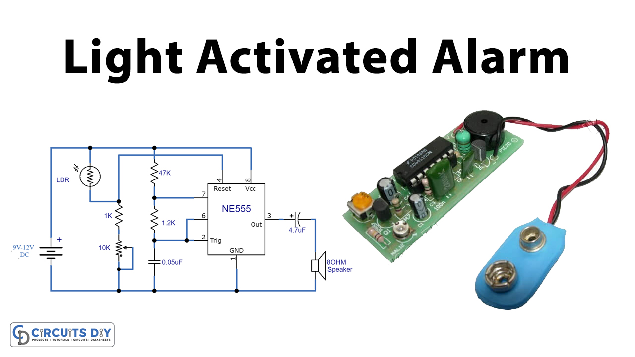
Light Activated Alarm Circuit
Working Explanation
As we all know, the LDR (Light Dependent Resistor) resistance is inversely proportional to the light intensity falling on it. It suggests that if the light intensity is high, the resistance of LDR will be less and vice versa. Therefore, this whole circuit fabricates on this basic principle of science.
Here in this circuit, a 10K variable resistor is utilized to modify the affectability of the circuit. However, an 8 ohms speaker is being used at the yield of the circuit to create sound. Changing the value of the 0.05uF capacitor can likewise change the sound frequency. The working voltage of the circuit is similarly set to be approximately 9V to 12V DC.
Then again, a 555 timer IC gets enacted when its reset (Pin-4) receives a voltage more noteworthy than 0.8V. When the IC is initiated, the voltage at Pins-2,6 should be between 1/third and 2/third of the applied voltage, for the yield to be ON. For instance, if the voltage at the reset pin is above 0.8V and the voltage at Pins-2,6 is a large portion of the applied voltage, the yield turns ON.
Hence, we have made a voltage divider utilizing LDR and a resistor + potentiometer. It is then associated with Pin-4 (reset) of 555 clock IC. So when it’s dark, the LDR’s resister rises; thus, the voltage at the voltage divider falls under 0.8V, making the 555 timer IC turn OFF. When there is sufficient light, the voltage at the reset pin goes above 0.8V, and the IC turns ON.
Applications and Uses
- Uses in light-sensitive rooms