Overview
This setup might seem simple, but it’s worth the time and energy. It offers a top-notch delay for interior lighting. While many new cars come with this feature built-in, the automatic dimmer version is usually reserved for pricier models. With this setup, you can enhance older or mid-tier cars by adding a delay to the interior lights that gradually fade out after you shut the door. The fading effect is achieved through pulse-width modulation, which involves using a triangle wave oscillator and a comparator.
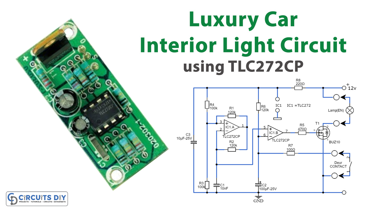
In today’s tutorial, we are going to make a “Luxury Car Interior Light Circuit” using a TLC272CP.
Hardware Components
You’ll need the following hardware components to get started:
| S no | Components | Value | Qty |
|---|---|---|---|
| 1 | Integrated Circuit IC | IC1 = TLC272CP | 1 |
| 2 | Transistors | T1 = BUZ10 | 1 |
| 3 | Capacitors | C1 = 10nF C2 = 100µF-25V C3 = 10µF-25V | 1 1 1 |
| 4 | Resistors | R1,R2,R6 = 120kΩ R3,R4 = 100kΩ R5 = 470Ω R7 = 100Ω R8 = 220Ω | 3 2 1 1 1 |
Schematic
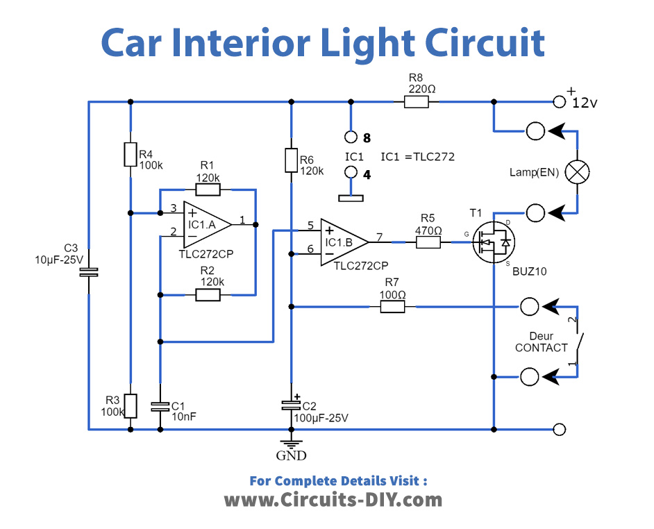
Typically, two operational amplifiers (opamps) are needed to create an accurate triangle wave. However, for our purposes where precision isn’t critical, we can manage with just one opamp. This leads to the configuration around IC1.A, forming a relaxation oscillator that produces a square wave output. The voltage at the inverting input takes on a more triangular shape. As long as we don’t overload it, this signal works well. The high impedance input of IC1.B ensures it doesn’t pose any issues in this regard. IC1.B functions as a comparator, comparing the voltage of the triangular wave with that from the door switch. When the door opens, the switch closes, creating a connection to the car’s chassis.
Once the door closes, the opamp’s output goes high, causing T1 to conduct and turn on the interior light. The light remains fully bright until the voltage across C2 drops to the lower end of the triangle wave (around 5 V). At this point, the comparator switches its output in sync with the triangle wave’s frequency (approximately 500 Hz), gradually reducing the pulse width. This gradual reduction in pulse width leads to a gradual decrease in the brightness of the interior light.
To protect against voltage spikes that might arise due to the rapid switching of the light, R8 and C3 are included in the circuit. The delay and dimming duration can be adjusted using R6 and C2; smaller values result in shorter durations. Additionally, you can independently adjust the dimming duration by tweaking R1, which alters the amplitude of the triangle wave across C1.
R7 plays a crucial role in limiting the discharge current of C2. If this resistance were too large, it would significantly shorten the lifespan of the capacitor. Fortunately, there’s no need to be concerned about this affecting the car battery’s longevity. The circuit draws just 350 µA when the lamp is off, especially when using a TLC272 for the dual opamp, or around 1 mA with a TL082. These values are unlikely to rapidly deplete a standard car battery; its self-discharge rate is likely much higher.
You can also opt for an LM358, TL072, or TL062 for IC1 without issues. In such cases, R8 should have a value between 47 Ω and 100 Ω. Since T1 operates in either fully on or fully off states, it generates minimal heat.
When the current reaches 2 A, the voltage drop across the transistor is approximately 100 mV, resulting in a dissipation of 200 mW. This level of dissipation is negligible, eliminating the need for a heatsink. Consequently, the entire circuit can remain compact and easily fit into the car, such as behind the fabric of the roof.