Introduction
A potentiometer fade LED code using an Arduino UNO microcontroller is a program that allows you to control the brightness of an LED using a potentiometer. The potentiometer is connected to an analog input pin on the microcontroller and the LED is connected to a digital output pin.
The program reads the value of the potentiometer, maps it to a value that can be used by the analogWrite() function, and uses that value to control the brightness of the LED. The program also allows for the status of the LED to be posted to the serial monitor, so the user can see the current status of the LED on the computer screen.
Hardware Components
You will require the following hardware for Potentiometer LED Fade with Arduino.
| S.no | Component | Value | Qty |
|---|---|---|---|
| 1. | Arduino UNO | – | 1 |
| 2. | USB Cable Type A to B | – | 1 |
| 3. | Potentiometer | – | 1 |
| 4. | Power Adapter for Arduino | 9V | 1 |
| 5. | LED | – | 1 |
| 6. | Resistor | 220Ω | 1 |
| 7. | Breadboard | – | 1 |
| 8. | Jumper Wires | – | 1 |
Potentiometer LED Fade with Arduino
- Initialize the pin numbers for the potentiometer and the LED: In the setup() function, the pin numbers for the potentiometer and the LED are defined using the const keyword. For example,
const int potentiometerPin = A0;
const int ledPin = 3;
- Setup the serial communication: In the setup() function, the Serial.begin() function is used to initialize serial communication at a specific baud rate, for example, 9600. This allows the microcontroller to communicate with the computer and post the status of the LED to the serial monitor. For example,
Serial.begin(9600);
- Add the pinModes: In the setup() function, the pin modes for the potentiometer and the LED are defined using the pinMode() function. The potentiometer is typically connected to an analog input pin and the LED is connected to a digital output pin. For example,
pinMode(potentiometerPin, INPUT);
pinMode(ledPin, OUTPUT);- Read the value of the potentiometer: In the loop() function, the analogRead() function is used to read the value of the potentiometer. This value is then stored in a variable, for example
potentiometerValue. For example,
int potentiometerValue = analogRead(potentiometerPin);
- Map the potentiometer value to a value that can be used by the analogWrite() function: The map() function is used to map the potentiometer value from the range of 0-1023 to the range of 0-255. For example,
int ledValue = map(potentiometerValue, 0, 1023, 0, 255);
- Control the LED: The microcontroller uses the analogWrite() function to control the brightness of the LED based on the mapped value. For example,
analogWrite(ledPin, ledValue);
- Post the status of the LED to the serial monitor: Using the Serial.print() function, the microcontroller sends the value of the potentiometer to the serial monitor. This allows the user to see the status of the LED on the computer screen. For example,
Serial.print("Potentiometer Value: ");
Serial.println(potentiometerValue);
- Add a delay: To prevent the serial monitor from being flooded with data, it’s a good idea to add a delay after sending the data to the serial monitor, for example delay(100);
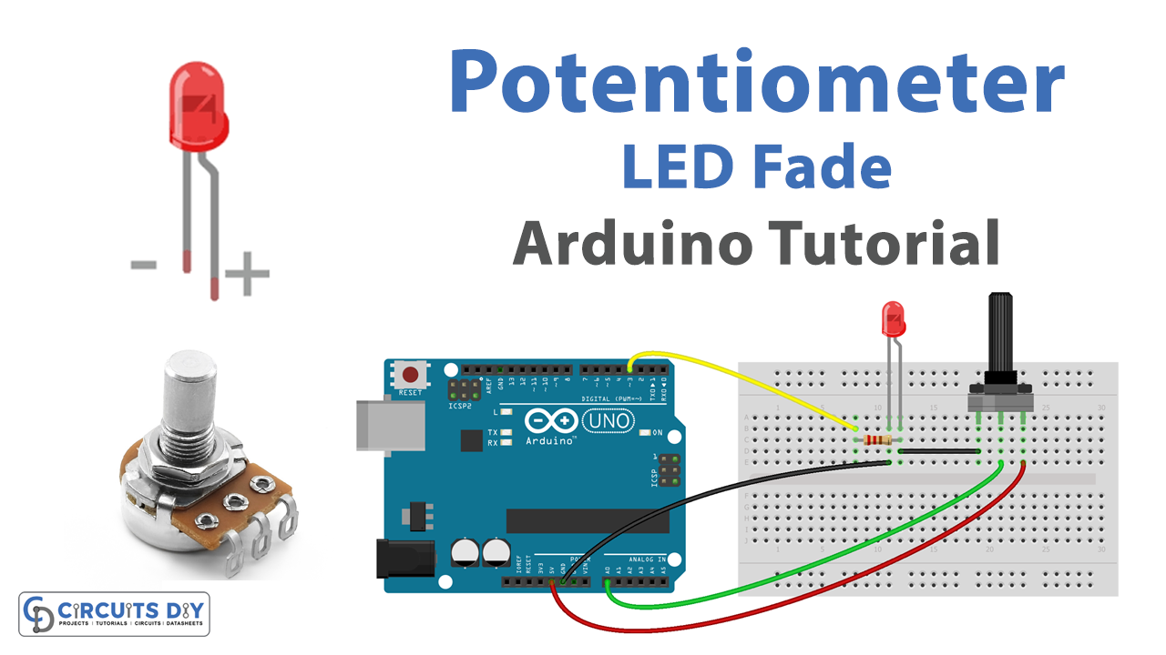
Schematic
Make connections according to the circuit diagram given below.

Wiring / Connections
| Arduino | Potentiometer | LED |
|---|---|---|
| 5V | Left | +VE with a 220-ohm resistor |
| GND | Right | GND |
| A0 | Wiper |
Installing Arduino IDE
First, you need to install Arduino IDE Software from its official website Arduino. Here is a simple step-by-step guide on “How to install Arduino IDE“.
Code
Now copy the following code and upload it to Arduino IDE Software.
int LED_PIN = 3;  // the PWM pin the LED is attached to

// the setup routine runs once when you press reset:
void setup() {
  // initialize serial communication at 9600 bits per second:
  Serial.begin(9600);

  // declare LED pin to be an output:
  pinMode(LED_PIN, OUTPUT);
}

// the loop routine runs over and over again forever:
void loop() {
  // reads the input on analog pin A0 (value between 0 and 1023)
  int analogValue = analogRead(A0);

  // scales it to brightness (value between 0 and 255)
  int brightness = map(analogValue, 0, 1023, 0, 255);

  // sets the brightness LED that connects to  pin 3
  analogWrite(LED_PIN, brightness);

  // print out the value
  Serial.print("Analog: ");
  Serial.print(analogValue);
  Serial.print(", Brightness: ");
  Serial.println(brightness);
  delay(100);
}
Working Explanation
When the program is running, it first sets up the pin modes for the potentiometer and the LED using the pinMode() function. The potentiometer is connected to an analog input pin and the LED is connected to a digital output pin. Then the code uses the Serial.begin() function to initialize serial communication at a specific baud rate, this allows the microcontroller to communicate with the computer and post the status of the LED to the serial monitor.
In the loop() function, the microcontroller uses the analogRead() function to read the value of the potentiometer. This value is then stored in a variable. The map function is used to map the potentiometer value from the range of 0-1023 to the range of 0-255, this is necessary because the analogWrite function takes a value between 0 and 255. The microcontroller then uses the analogWrite() function to control the brightness of the LED based on the mapped value. The analogWrite() function takes a value between 0 and 255, where 0 is the lowest brightness and 255 is the highest.
Applications
- Lighting control
- Industrial control
- Photography and Videography
- Musical instruments
- Robotics
- Automotive
- Signs and displays
Conclusion.
We hope you have found this Potentiometer Fade LED Circuit very useful. If you feel any difficulty in making it feel free to ask anything in the comment section.