Introduction
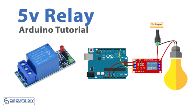
To generates the time delay functions in the electronic circuits, there is a component called ‘relay’ that is used. It isolates the low voltage circuit from a high voltage circuit. It’s an electromagnetic switch that provides an electrical connection between two points to control a circuit or a device. Telegraphs were the first application that used these relays. But, now every other electronic device has these relays. Since, as an electronic engineer, it fascinates us to control our home appliances like AC, fans, TV, etc from ourselves by using Arduino coding. But, Arduino doesn’t support high voltages. Therefore, relay plays a crucial role there. Today’s article is all about that. In this tutorial, we are going to interface “2 Channel Relay Module with Arduino UNO”. However, before making this project we must have to see that how relays work.

An Overview About the Working of Relays
When there are no current flows in the circuit, no magnetic field occurs. Hence, the circuit will be OFF. When a small current flows, it active the electromagnet to induces the magnetic field around it. And, this closes the switch, allows the greater current to flow through this. Hence the device works. When the current stop flowing, the circuit will be OFF again.
Hardware Required
| S.no | Component | Value | Qty |
|---|---|---|---|
| 1. | Arduino | UNO | 1 |
| 2. | USB Cable Type A to B | – | 1 |
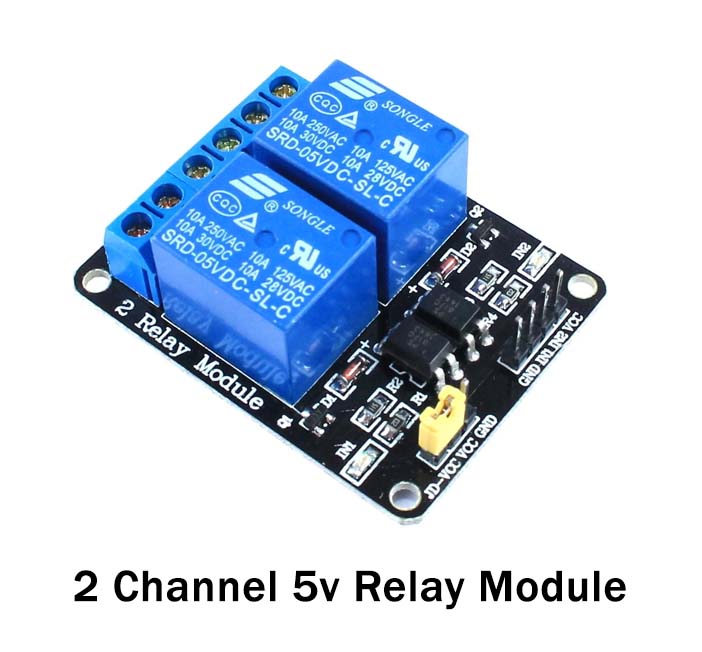
| 3. | 2 Channel Relay Module | – | 1 |
| 4. | AC Bulb | 220V | 1 |
| 5. | Jumper Wires | – | 1 |
| 6. | DC Power for Arduino | – | 1 |
Circuit Diagram
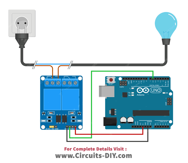
Connection Table
| Arduino | Relay Module | AC Bulb | AC Power |
|---|---|---|---|
| GND | GND | ||
| D6 | IN1 | ||
| 5V | VCC | ||
| NO1 | Line | ||
| Neutral | Neutral | ||
| COM1 | Line |
Arduino Code
// Circuits DIY
// For Details Visit -> https://circuits-diy.com

int RelayPin = 6;

void setup() {
	// Set RelayPin as an output pin
	pinMode(RelayPin, OUTPUT);
}

void loop() {
	// Let's turn on the relay...
	digitalWrite(RelayPin, LOW);
	delay(3000);

	// Let's turn off the relay...
	digitalWrite(RelayPin, HIGH);
	delay(3000);
}
Working Explanation
To understand the working of the relay module with Arduino UNO, first, you need to understand the pin configuration of the two-channel relay module. The module contains four control pins that are pin 1, 2, 3, and 4. Pin 1 is the power supply pin to power the optocoupler in the module. Pin 4 is for the ground. While pin 2, and 3 is to control the relay. Pin 5, 6, and, 7 are the power supply selection pins. While pin 8 to 13 are the output terminal pins.
Now, coming towards the circuit, connect the Vcc pin of the module to the 5-volt pin of an Arduino. Connect the ground pin of the relay module to the ground of an Arduino. Cut your AC line of the appliance and connect its one end to the COM pin of the module. Now, if you want your device to mostly to remain OFF, then connect it with the NO pin of the module. However, if you want the device to remain ON most of the time, connect to its other end to the NC of the module. In other words, this connection depends on you that what you need the resting state of your device. To clarify, in this project we want the resting state to be OFf, so we are connecting that end to NO pin. And, that’s how the circuit got wired for your devices
Code Explanation
After the circuit got its connection, here we need to work on the code. The code is already mentioned above. First, we have declared the pin through which the input pin of the module is connected and that is pin 6 of an Arduino. Then, we have defined that pin as the output of the circuit. Now, using the loop function we have defined to turn ON and OFF the device. This is how the code works.
Application and Uses
This particular device can be used to control any AC appliances in your home. Therefore, it can be used in home, office, and industrial automation circuits. With some modification, it can be used in other electronic circuits too.