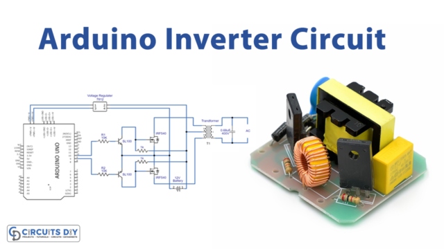
Introduction
Suppose you’re making a project that operates on DC but suddenly you got the realization that you need an AC component for your circuit. May be an AC light or an AC motor. What would you do? Now, you need an AC supply for that but your device has a DC supply. So, you require an AC inverter circuit. With some modification, we can also adopt the following circuit in UPS and other DC to AC converter applications. So, in this tutorial, we are going to make an ” Arduino Inverter Circuit “. To understand the whole circuitry let us first discuss Arduino.
Pin Configuration of Arduino
- Digital i/o Pins: There are 54 digital input/output pins of which 15 are Pulse width modulation pins from pin 2 to pin 13 and from pin 44 to pin 46. The digital input/output pins also contain 10 communication Pins from pins 14 to 21 including pins 0 and 1. They are basically used to exchange the data between Arduino and the other devices like sensors, etc.
- Analog input/output Pins: There are 16 analog input/output pins from A0 to A15. For the sensor, to get the data, these pins are used as input. For the modules or motors used as output.
- Power and ground pins Pins: Some power pins are also there just like Arduino UNO to power the board. It has three power pins and there are 7 ground pins on the board. Moreover, there are other pins of 5V and 3.3V. Further, there is a reset pin to reset the program on the board.
Hardware Required
| S.no | Component | Value | Qty |
|---|---|---|---|
| 1. | Arduino | UNO | 1 |
| 2. | USB Cable Type A to B | – | 1 |
| 3. | IRF | 540 | 2 |
| 4. | Transistor | SL100 | 2 |
| 5. | Transformer | 12-0-12 | 1 |
| 6. | Voltage Regulator | 7805 | 1 |
| 7. | Resistor | 1K, 10K | 2,2 |
| 8. | LCD | 1602 | 1 |
| 9. | Jumper Wires | – | – |
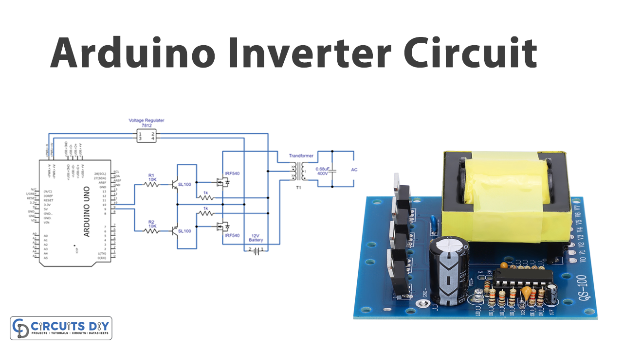
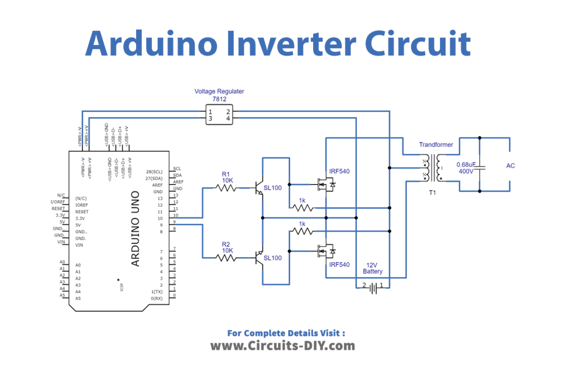
Circuit Diagram
Connection Table
| Arduino | IC 7805 |
|---|---|
| GND | GND |
| 5V | Vcc |
| D1 | DT |
| D2 | CLK |
Arduino Code
const int SpwmArry[] = {500,500,750,500,1250,500,2000,500,1250,500,750,500,500}; // Array of SPWM values.
const int SpwmArryValues = 13; //Put length of an Array depends on SpwmArray numbers.
// Declare the output pins and choose PWM pins only
const int sPWMpin1 = 10;
const int sPWMpin2 = 9;
// enabling bool status of Spwm pins
bool sPWMpin1Status = true;
bool sPWMpin2Status = true;

void setup()
{
 pinMode(sPWMpin1, OUTPUT);
 pinMode(sPWMpin2, OUTPUT);
}

void loop()
{
 // Loop for Spwm pin 1
 for(int i(0); i != SpwmArryValues; i++)
 {
  if(sPWMpin1Status)
  {
   digitalWrite(sPWMpin1, HIGH);
   delayMicroseconds(SpwmArry[i]);
   sPWMpin1Status = false;
  }
  else
  {
   digitalWrite(sPWMpin1, LOW);
   delayMicroseconds(SpwmArry[i]);
   sPWMpin1Status = true;
  }
 }

 // Loop for Spwm pin 2
 for(int i(0); i != SpwmArryValues; i++)
 {
  if(sPWMpin2Status)
  {
   digitalWrite(sPWMpin2, HIGH);
   delayMicroseconds(SpwmArry[i]);
   sPWMpin2Status = false;
  }
  else
  {
   digitalWrite(sPWMpin2, LOW);
   delayMicroseconds(SpwmArry[i]);
   sPWMpin2Status = true;
  }
 }
}
Working Explanation
This Arduino Inverter Circuit has three main stages. The first stage of this circuit is the Arduino Microcontroller board and we program it to give Sinusoidal Pulse Width Modulation (SPWM) or you can change the code to get different output from Arduino pins. The second stage is the switching and driver stage, we feed the output pulse from the Arduino digital pins into switching transistor SL100 NPN and then power MOSFET IRF540. The third stage is an output stage which is constructed by using a center-tapped transformer (230 VAC primary 12-0-12 VAC secondary) and it is wired reversely with a driver circuit that is a second stage is connected to the power MOSFET and primary side of the transformer let to give output supply.
When the battery is connected with this circuit voltage regulator 7812 powers up the Arduino board and it starts producing output pulses depending on the sketch, the pulses drive the transistor SL100 and power MOSFET IRF540, and the transformer secondary winding connected with the MOSFET gets discrete energy and mutually induce much primary winding, as we know due to large numbers of winding and changing magnetic field, it produces high voltage AC output.
Code Explanation
- First, you need to define an array, the length of the array, input and output pins, and the status of pins.
- In void setup, define the output pin modes.
- In a void loop, write the if else condition to declare the condition of SPWM.
Application and Uses
- Power supplies.
- UPS circuits.
- To operate AC devices like AC fans, light, etc.