Introduction
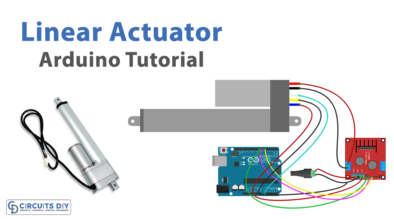
Interfacing a linear actuator with an Arduino UNO for feedback control allows for precise and accurate control of the actuator’s position. By using a feedback mechanism, such as a potentiometer or an encoder, the Arduino can constantly monitor the actuator’s position and make adjustments to maintain a desired position or trajectory. This opens up a wide range of possibilities for applications in robotics, automation, and other fields where precise control of linear motion is necessary.
The L12-P Micro Linear Actuator is a small and powerful linear actuator designed for precision applications. The L12-P Micro Linear Actuator has a compact design, with a body diameter of 12mm (0.47 inches) and a stroke length of up to 100mm (3.94 inches). It is equipped with a built-in potentiometer for position feedback, which allows for precise control over the actuator’s movement. The actuator is driven by a 12V DC power supply and can handle a maximum load of 50N (11.24 lbs). It has a maximum speed of 35mm/s (1.38 inches/s) and a positional accuracy of 0.05mm (0.002 inches).
Hardware Components
You will require the following hardware for Linear Actuator with Feedback.
| S.no | Component | Value | Qty |
|---|---|---|---|
| 1. | Arduino UNO | – | 1 |
| 2. | USB Cable Type A to B | – | 1 |
| 3. | Linear Actuator with Feedback | 12V | 1 |
| 4. | Motor Driver Module | L298N | 1 |
| 5. | Power Adapter | 12V- | 1 |
| 6. | DC Power Jack | – | 1 |
| 7. | Power Adapter for Arduino | 9V | 1 |
| 8. | Jumper Wires | – | 1 |
Linear Actuator with Feedback
- Define the pin connections used in the code
#define ENA_PIN   7 // the Arduino pin connected to the EN1 pin L298N
#define IN1_PIN   6 // the Arduino pin connected to the IN1 pin L298N
#define IN2_PIN   5 // the Arduino pin connected to the IN2 pin L298N
#define POTENTIOMETER_PIN   A0 // the Arduino pin connected to the potentiometer of the actuator
- Initialize the serial communication and set the pin modes in the
setup()function
void setup() {
  Serial.begin(9600);
  pinMode(ENA_PIN, OUTPUT);
  pinMode(IN1_PIN, OUTPUT);
  pinMode(IN2_PIN, OUTPUT);
  digitalWrite(ENA_PIN, HIGH);
}
- In the
loop()function, extend the actuator by setting the direction of the motor withdigitalWrite(). Then, wait for the actuator to fully extend using thedelay()function. After the actuator stops, read the analog value of the potentiometer and print it to the serial monitor.
// extend the actuator
digitalWrite(IN1_PIN, HIGH);
digitalWrite(IN2_PIN, LOW);
delay(20000); // wait for actuator fully extends. It will stop extending automatically when reaching the limit
// read the analog in value:
int POTENTIOMETER_MAX = analogRead(POTENTIOMETER_PIN);
Serial.print("POTENTIOMETER_MAX = ");
Serial.println(POTENTIOMETER_MAX);
- Retract the actuator by setting the direction of the motor in the opposite direction. Wait for the actuator to fully retract using the
delay()function. After the actuator stops, read the analog value of the potentiometer and print it to the serial monitor.
// retracts the actuator
digitalWrite(IN1_PIN, LOW);
digitalWrite(IN2_PIN, HIGH);
delay(20000); // wait for actuator fully extends. It will stop retracting automatically when reaching the limit
int POTENTIOMETER_MIN = analogRead(POTENTIOMETER_PIN);
Serial.print("POTENTIOMETER_MIN = ");
Serial.println(POTENTIOMETER_MIN);
Schematic
Make connections according to the circuit diagram given below.

Wiring / Connections
| Arduino | Linear Actuator | L298n MOTOR |
|---|---|---|
| 5V | PIN 1 (RED) | VCC |
| GND | PIN 2 (BLACK) | GND |
| A0 | PIN3 (S.GREEN) | |
| PIN 4 (BLACK) | OUT 1 | |
| PIN5 (RED) | OUT 2 | |
| D7 | ENABLED | |
| D6 | IN 1 | |
| D5 | IN 2 |
Installing Arduino IDE
First, you need to install Arduino IDE Software from its official website Arduino. Here is a simple step-by-step guide on “How to install Arduino IDE“
Code
Now copy the following code and upload it to Arduino IDE Software.
#define ENA_PIN   7 // the Arduino pin connected to the EN1 pin L298N
#define IN1_PIN   6 // the Arduino pin connected to the IN1 pin L298N
#define IN2_PIN   5 // the Arduino pin connected to the IN2 pin L298N
#define POTENTIOMETER_PIN   A0 // the Arduino pin connected to the potentiometer of the actuator

void setup() {
  Serial.begin(9600);
  // initialize digital pins as outputs.
  pinMode(ENA_PIN, OUTPUT);
  pinMode(IN1_PIN, OUTPUT);
  pinMode(IN2_PIN, OUTPUT);

  digitalWrite(ENA_PIN, HIGH);
}

void loop() {
  // extend the actuator
  digitalWrite(IN1_PIN, HIGH);
  digitalWrite(IN2_PIN, LOW);
  delay(20000); // wait for actuator fully extends. It will stop extending automatically when reaching the limit
  // read the analog in value:
  int POTENTIOMETER_MAX = analogRead(POTENTIOMETER_PIN);
  Serial.print("POTENTIOMETER_MAX = ");
  Serial.println(POTENTIOMETER_MAX);

  // retracts the actuator
  digitalWrite(IN1_PIN, LOW);
  digitalWrite(IN2_PIN, HIGH);
  delay(20000); // wait for actuator fully extends. It will stop retracting automatically when reaching the limit
  int POTENTIOMETER_MIN = analogRead(POTENTIOMETER_PIN);
  Serial.print("POTENTIOMETER_MIN = ");
  Serial.println(POTENTIOMETER_MIN);
}
Arduino code that calculates the position of the actuator
#define ENA_PIN   7 // the Arduino pin connected to the EN1 pin L298N
#define IN1_PIN   6 // the Arduino pin connected to the IN1 pin L298N
#define IN2_PIN   5 // the Arduino pin connected to the IN2 pin L298N
#define POTENTIOMETER_PIN   A0 // the Arduino pin connected to the potentiometer of the actuator

#define STROKE_LENGTH      102 // PLEASE UPDATE THIS VALUE (in millimeter)
#define POTENTIOMETER_MAX  987   // PLEASE UPDATE THIS VALUE
#define POTENTIOMETER_MIN  13    // PLEASE UPDATE THIS VALUE

void setup() {
  Serial.begin(9600);
  // initialize digital pins as outputs.
  pinMode(ENA_PIN, OUTPUT);
  pinMode(IN1_PIN, OUTPUT);
  pinMode(IN2_PIN, OUTPUT);

  digitalWrite(ENA_PIN, HIGH);
}

void loop() {
  // extend the actuator
  digitalWrite(IN1_PIN, HIGH);
  digitalWrite(IN2_PIN, LOW);

  int potentiometer_value = analogRead(POTENTIOMETER_PIN);
  int stroke_pos = map(potentiometer_value, POTENTIOMETER_MIN, POTENTIOMETER_MAX, 0, STROKE_LENGTH);
  Serial.print("The stroke's position = ");
  Serial.print(stroke_pos);
  Serial.println(" mm");
}
Working Explanation
In the setup() function, the serial communication is initiated at 9600 bits per second, and the pins ENA_PIN, IN1_PIN, and IN2_PIN are initialized as outputs. The ENA_PIN is set to HIGH to enable the L298N driver. In the loop() function, the actuator is first extended by setting the IN1_PIN to HIGH and the IN2_PIN to LOW. The actuator will stop extending automatically when reaching the limit, which is set to 20 seconds by the delay(20000) function.
After the actuator has fully extended, the voltage on the potentiometer is read and stored in the POTENTIOMETER_MAX variable. Then, the actuator is retracted by setting the IN1_PIN to LOW and the IN2_PIN to HIGH. The actuator will stop retracting automatically when reaching the limit, which is set to 20 seconds by the delay(20000) function. After the actuator has fully retracted, the voltage on the potentiometer is read and stored in the POTENTIOMETER_MIN variable. Finally, the POTENTIOMETER_MAX and POTENTIOMETER_MIN values are printed to the serial monitor for debugging purposes.
Applications
- Automation
- Medical devices
- Automotive
- Aerospace
- Industrial machinery
- Home automation
- Entertainment systems
- Farming equipment
- Construction Equipment
Conclusion.
We hope you have found this Linear Actuator with Feedback Circuit very useful. If you feel any difficulty in making it feel free to ask anything in the comment section.