Introduction
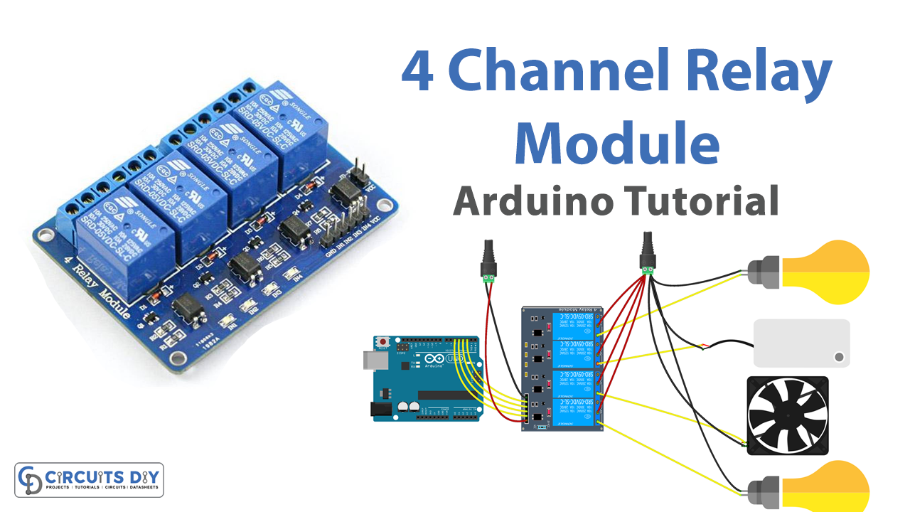
Interfacing a 4-channel relay with an Arduino Uno is a simple and efficient way to control AC/DC appliances. A relay is an electrically operated switch that can be controlled by an Arduino board, allowing you to turn appliances on and off remotely. It is important to note that, for safety reasons, the relay module should be connected to an external power supply and not to the Arduino board, as the amount of current required by the appliances may damage the board.
In today’s tutorial, we will learn how to control multiple appliances with a Tolako 5V 4 Channel Solid State Relay using an Arduino UNO microcontroller.
Hardware Components
You will require the following hardware for the Interfacing 4 Channel Relay Module with Arduino.
| S.no | Component | Value | Qty |
|---|---|---|---|
| 1. | Arduino UNO | – | 1 |
| 2. | USB Cable Type A to B | – | 1 |
| 3. | 4-Channel Relay Module | – | 1 |
| 4. | Power Adapter for Arduino | 9V | 1 |
| 5. | Jumper Wires | – | 1 |
4-Channel Relay Module with Arduino
- Connect the 4-Channel relay module to the Arduino: Connect the SSR module to the Arduino according to the pinout diagram provided by the manufacturer. Typically, the SSR module will have 4 control pins (IN1, IN2, IN3, IN4) that need to be connected to digital pins on the Arduino, and the module will also have power and ground pins that need to be connected to the appropriate power and ground pins on the Arduino.
- Define the pin numbers for the 4-Channel relay module and appliances in the code: In the code, define the pin numbers for the control pins of the SSR module (IN1, IN2, IN3, IN4) and the appliances (AC Bulb, AC Fan, AC motor). For example:
#define AC_BULB_PIN 8
#define AC_FAN_PIN 9
#define AC_MOTOR_PIN 10
#define SSR_IN1_PIN 2
#define SSR_IN2_PIN 3
#define SSR_IN3_PIN 4
#define SSR_IN4_PIN 5
- Set the pin modes in the setup function: In the setup function, set the pin modes for the control pins of the 4-Channel relay module and the appliances. For example:
pinMode(SSR_IN1_PIN, OUTPUT);
pinMode(SSR_IN2_PIN, OUTPUT);
pinMode(SSR_IN3_PIN, OUTPUT);
pinMode(SSR_IN4_PIN, OUTPUT);
pinMode(AC_BULB_PIN, OUTPUT);
pinMode(AC_FAN_PIN, OUTPUT);
pinMode(AC_MOTOR_PIN, OUTPUT);
- Control the appliances in the loop function: In the loop function, write code to control the appliances using the control pins of the 4-Channel relay module. For example, to turn on the AC bulb, you would write:
digitalWrite(SSR_IN1_PIN, HIGH);
and to turn off the AC bulb, you would write:
digitalWrite(SSR_IN1_PIN, LOW);
similarly you can control the other appliances by using the respective IN pins of the 4-Channel relay.
- Add Serial monitor code to post the status of each appliance: In the loop function, add code to send the status of each appliance to the serial monitor. For example, you can use the
Serial.println()function to print messages such as “AC bulb on” or “AC fan off” to the serial monitor.
if (digitalRead(SSR_IN1_PIN) == HIGH) {
    Serial.println("AC bulb is on");
} else {
    Serial.println("AC bulb is off");
}
- Use of function: To make the code more readable and organized, you can create functions to control the appliances and the status of appliances, instead of using the if-else statements in the loop function.
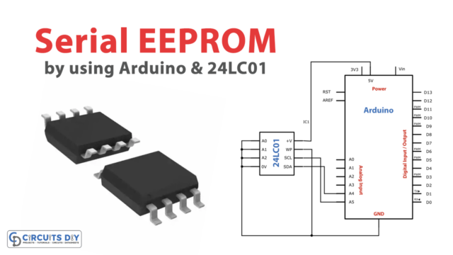
Schematic
Make connections according to the circuit diagram given below.
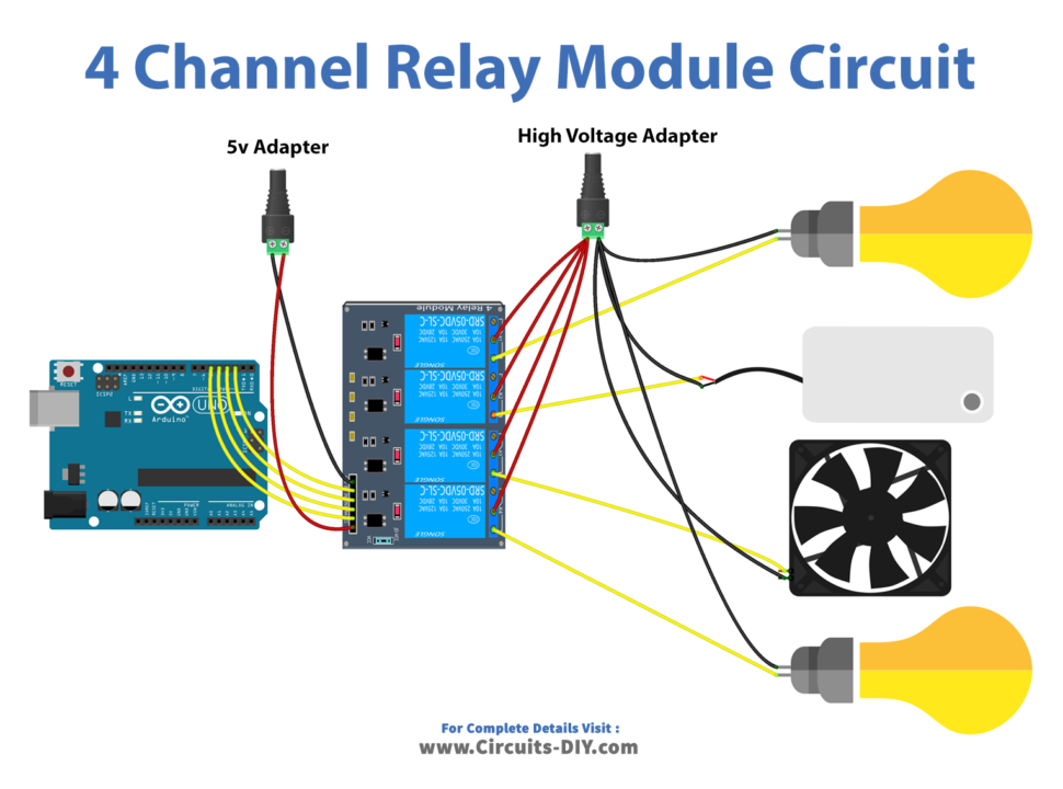
Wiring / Connections
| Arduino | Relay Module |
|---|---|
| GND | DC- |
| 5V | DC+ |
| D2 | IN1 |
| D3 | IN2 |
| D4 | IN3 |
| D5 | IN4 |
Installing Arduino IDE
First, you need to install Arduino IDE Software from its official website Arduino. Here is a simple step-by-step guide on “How to install Arduino IDE“.
Code
Now copy the following code and upload it to Arduino IDE Software.
#define PIN_RELAY_1  2 // the Arduino pin, which connects to the IN1 pin of relay module
#define PIN_RELAY_2  3 // the Arduino pin, which connects to the IN2 pin of relay module
#define PIN_RELAY_3  4 // the Arduino pin, which connects to the IN3 pin of relay module
#define PIN_RELAY_4  5 // the Arduino pin, which connects to the IN4 pin of relay module

// the setup function runs once when you press reset or power the board
void setup() {
  Serial.begin(9600);

  // initialize digital pin as an output.
  pinMode(PIN_RELAY_1, OUTPUT);
  pinMode(PIN_RELAY_2, OUTPUT);
  pinMode(PIN_RELAY_3, OUTPUT);
  pinMode(PIN_RELAY_4, OUTPUT);
}

// the loop function runs over and over again forever
void loop() {
  Serial.println("Turn on all");
  digitalWrite(PIN_RELAY_1, HIGH);
  digitalWrite(PIN_RELAY_2, HIGH);
  digitalWrite(PIN_RELAY_3, HIGH);
  digitalWrite(PIN_RELAY_4, HIGH);
  delay(1000);

  Serial.println("Turn off all");
  digitalWrite(PIN_RELAY_1, LOW);
  digitalWrite(PIN_RELAY_2, LOW);
  digitalWrite(PIN_RELAY_3, LOW);
  digitalWrite(PIN_RELAY_4, LOW);
  delay(1000);
}
Working Explanation
The first step is to connect the SSR module to the Arduino according to the pinout diagram provided by the manufacturer. The control pins of the SSR module (IN1, IN2, IN3, IN4) are connected to digital pins on the Arduino and the module’s power and ground pins are connected to the appropriate power and ground pins on the Arduino.
In the code, the pin numbers for the control pins of the SSR module and the appliances are defined and the pin modes are set in the setup function. In the loop function, the code uses the digital write function to control the appliances using the control pins of the SSR module. For example, to turn on the AC bulb, the code would write a high signal to the IN1 pin of the SSR module. To turn off the AC bulb, the code would write a low signal to the IN1 pin of the SSR module.
Applications
- Medical equipment
- Theme parks
- Photography
- Marine industry
- Water treatment
- Military and defense
- Mining industry
Conclusion.
We hope you have found this 4-Channel Relay Module Circuit very useful. If you feel any difficulty in making it feel free to ask anything in the comment section.