Introduction
A momentary pushbutton-controlled LED using an Arduino UNO is a system that uses a pushbutton and an LED connected to an Arduino microcontroller to control the state of the LED. A pushbutton is a type of switch that is activated when it is pressed and deactivated when it is released.
In a momentary pushbutton-controlled LED system, the Arduino reads the state of the pushbutton using a digital input pin and controls the state of the LED using an output pin. When the pushbutton is pressed, the Arduino sends a HIGH signal to the LED, turning it on. When the pushbutton is released, the Arduino sends a LOW signal to the LED, turning it off.
Hardware Components
You will require the following hardware for Button Toggle LED with Arduino.
| S.no | Component | Value | Qty |
|---|---|---|---|
| 1. | Arduino UNO | – | 1 |
| 2. | USB Cable Type A to B | – | 1 |
| 3. | Button | – | 1 |
| 4. | 9V Power Adapter for Arduino | – | 1 |
| 5. | LED | – | 1 |
| 6. | Resistor | 220Ω | 1 |
| 7. | Breadboard | – | 1 |
| 8 | Jumper Wires | – | 1 |
Steps Button Toggle LED with Arduino UNO
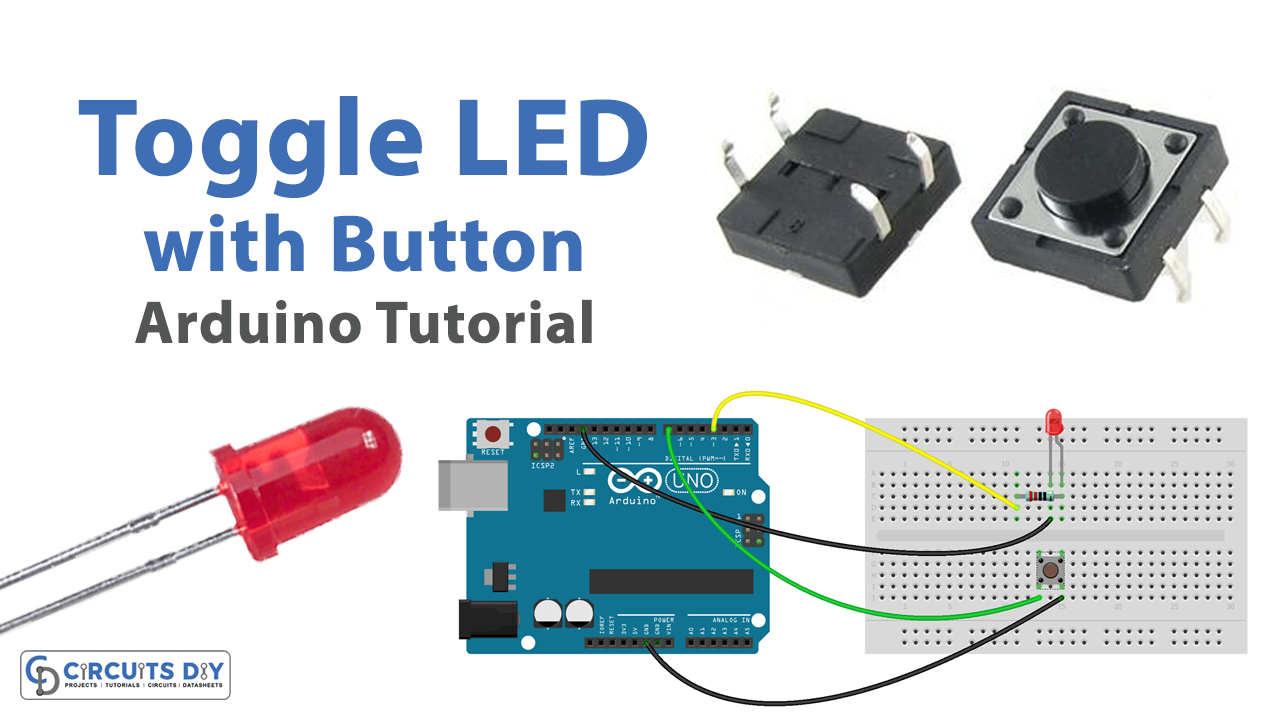
- Connect the LED to the breadboard. Connect the shorter leg of the LED to a row on the breadboard, and the longer leg to a different row. If you are using a 220-ohm resistor, connect it between the LED and the breadboard row as well.
- Connect the pushbutton to the breadboard. Connect one end of the pushbutton to a row on the breadboard and the other end to a different row.
- Connect the breadboard to the Arduino. Connect one end of a jumper wire to the row with the shorter leg of the LED and the other end to a digital output pin on the Arduino. Now, Connect another jumper wire from the row with the longer leg of the LED to a ground pin on the Arduino. After this, Connect one end of a jumper wire to one row of the pushbutton, and the other end to a digital input pin on the Arduino.
- Connect another jumper wire from the other row of the pushbutton to a power supply pin on the Arduino.
- Open the Arduino software on your computer and create a new sketch by clicking “File” and then “New.”
- Set the pin modes for the digital input and output pins that the pushbutton and LED are connected to by adding the following lines of code at the beginning of the sketch:
pinMode(buttonPin, INPUT);
pinMode(ledPin, OUTPUT);
Replace “buttonPin” and “ledPin” with the actual numbers of the digital input and output pins that the pushbutton and LED are connected to.
- In the loop function, add the following lines of code to turn the LED on and off based on the state of the pushbutton:
int buttonState = digitalRead(buttonPin);
if (buttonState == HIGH) {
digitalWrite(ledPin, HIGH);
} else {
digitalWrite(ledPin, LOW);
}
Replace “buttonPin” and “ledPin” with the actual numbers of the digital input and output pins
Schematic
Make connections according to the circuit diagram given below.
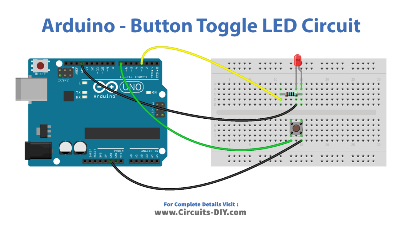
Wiring / Connections
| Arduino | Button | LED |
|---|---|---|
| GND | One End | -ve leg |
| D3 | +ve with resistor | |
| D7 | Other End |
Installing Arduino IDE
First, you need to install Arduino IDE Software from its official website Arduino. Here is a simple step-by-step guide on “How to install Arduino IDE“.
Installing Libraries
Before you start uploading a code, download and unzip the following libraries at /Progam Files(x86)/Arduino/Libraries (default), in order to use the sensor with the Arduino board. Here is a simple step-by-step guide on “How to Add Libraries in Arduino IDE“.
Code
Now copy the following code and upload it to Arduino IDE Software.
Arduino Code – Button Toggles LED Without Debouncing
const int BUTTON_PIN = 7; // Arduino pin connected to button's pin
const int LED_PIN    = 3; // Arduino pin connected to LED's pin

// variables will change:
int ledState = LOW;     // the current state of LED
int lastButtonState;    // the previous state of button
int currentButtonState; // the current state of button

void setup() {
  Serial.begin(9600);                // initialize serial
  pinMode(BUTTON_PIN, INPUT_PULLUP); // set arduino pin to input pull-up mode
  pinMode(LED_PIN, OUTPUT);          // set arduino pin to output mode

  currentButtonState = digitalRead(BUTTON_PIN);
}

void loop() {
  lastButtonState    = currentButtonState;      // save the last state
  currentButtonState = digitalRead(BUTTON_PIN); // read new state

  if(lastButtonState == HIGH && currentButtonState == LOW) {
    Serial.println("The button is pressed");

    // toggle state of LED
    ledState = !ledState;

    // control LED arccoding to the toggled state
    digitalWrite(LED_PIN, ledState);
  }
}
Arduino Code – Button Toggles LED With Debouncing
#include <ezButton.h>

/// constants won't change
const int BUTTON_PIN = 7; // the number of the pushbutton pin
const int LED_PIN    = 3; // the number of the LED pin

ezButton button(BUTTON_PIN);  // create ezButton object that attach to pin 7;

// variables will change:
int ledState = LOW;   // the current state of LED

void setup() {
  Serial.begin(9600);         // initialize serial
  pinMode(LED_PIN, OUTPUT);   // set arduino pin to output mode
  button.setDebounceTime(50); // set debounce time to 50 milliseconds
}

void loop() {
  button.loop(); // MUST call the loop() function first

  if(button.isPressed()) {
    Serial.println("The button is pressed");

    // toggle state of LED
    ledState = !ledState;

    // control LED arccoding to the toggleed sate
    digitalWrite(LED_PIN, ledState);
  }
}
Working Explanation
The working of these circuits is as follows: In the setup function, the pin modes for the pushbutton and LED pins are set to INPUT and OUTPUT, respectively, using the pinMode function. In the loop function, the state of the pushbutton is read using the digitalRead function.
To toggle the state of the LED, the code uses a variable to keep track of the current state of the LED. This variable is initialized to LOW in the setup function, and its value is toggled every time the pushbutton is pressed. When the pushbutton is pressed, the code checks the current state of the LED. If the LED is currently off (LOW), the code turns it on (HIGH) and updates the variable to reflect the new state. If the LED is currently on (HIGH), the code turns it off (LOW) and updates the variable to reflect the new state.
Applications
- Lighting control
- Educational tool
- Prototype development
- Art installation
- On/off switch for a device or system
- Notification indicator
- Status indicator
Conclusion.
We hope you have found this Button Toggle LED Circuit very useful. If you feel any difficulty in making it feel free to ask anything in the comment section.