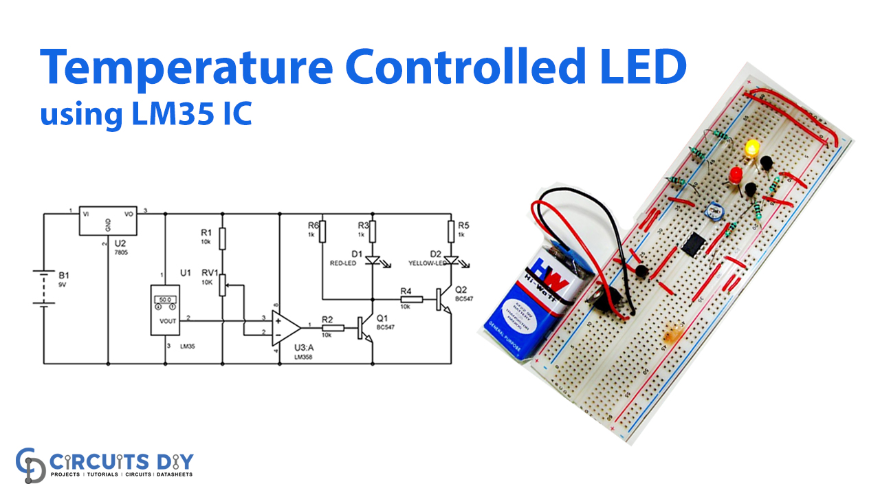
Today a fundamental but advantageous circuit is now being built with the LM35 temperature sensor. We also can adjust the LEDs as per the temperature on just this circuit. Unless the temperature reaches a certain amount (50 ° c throughout this circuit), the Red LED typically glows; meanwhile, the yellow LED is below that particular temperature. By adjusting the voltage divider in the circuit, this threshold value can be specified as deemed necessary.
Hardware Component
The following components are required to make Temperature Controlled LEDs Circuit
| S.no | Component | Value | Qty |
|---|---|---|---|
| 1. | Temperature sensor | LM35 | 1 |
| 2. | Op-amp | LM358 | 1 |
| 3. | IC | 7805 | 1 |
| 4. | Battery | 9v | 1 |
| 5. | Resistor | 1K, 10K, 10k Var | 3, 3, 1 |
| 6. | LEDs (Red and Yellow) | – | 1 |
| 7. | NPN Transistor | BC547 | 2 |
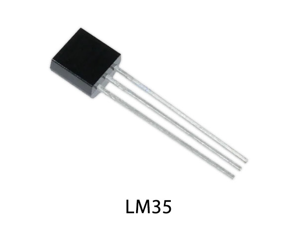
LM35 Pinout

For a detailed description of pinout, dimension features, and specifications download the datasheet of LM35
LM358 Pinout

For a detailed description of pinout, dimension features, and specifications download the datasheet of LM358
Temperature-Controlled LEDs Circuit
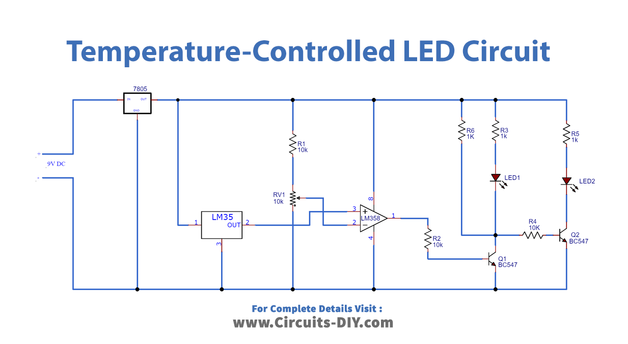
Circuit Operation
Generally, It’s comfortable to manage with the project Temperature Controlled Lights. The 9v battery is used to power up the load resistor and IC7805 to supply 5v to the circuit regulated. If the temperature is below 50oC, the yellow LED will be on, and the RED will be OFF. LOW remains the LM358 output, Q2 remains in OFF, and transistor Q2 remains in ON state when the temperature is below 50 ° c.
Now that the temperature around is above 50 ° C, LM35 power output at pin 2 will also be above 0.5 volts or 500 mV. The LM35 output is connected to the LM358 Pin 3. So the reference voltage set at Pin 2 (LM358 volt), the voltage set at Pin 3 (not inverted input) is more significant than Pin 2 (inverted input), and the LM358 (PIN 1) output is greater than the voltages at Pin 2 (inverted input). LM358 output, related to the NPN transistor base Q1, indicates that Q1 also gets on, and Red LED begins to reflect light. The transistor Q2 base is also grounding, Q2 is OFF, and the yellow LED is also OFF. Thus by illuminating the red LED, the circuit senses the power transfer capability.
Applications and Uses
- As a temperature sensor, the popular IC LM35 is used here. LM35 performance rises in temperature by 10 mV per degree rise.
- This Light Circuit Temperature Control can be used in several ways, such as as an indication of a temperature, or can cause devices like a fan or a doorbell above a specific temperature.