Introduction
The world is growing fast in terms of technology, and as it’s growing, it’s also getting wireless. From wireless phones to wireless chargers, humans try to minimize the use of wires. So taking that into mind, we decided that in this tutorial, we would make a “wireless LED circuit.” An LED display that does not require wires or cables is known as a wireless LED display.
The circuit is relatively easy to construct for newbies and only needs a few essential components. It operates on the principle of inductive coupling, which is the wireless transport of electrical energy, in this case, using magnetic flux coupled coils.
Hardware Required
| S.no | Component | Value | Qty |
|---|---|---|---|
| 1. | Tx-Coil (Coil copper wire with 6CM dia / 15 turns) | – | 1 |
| 2. | Rx-Coil (Coil copper wire with 6CM dia / 30 turns) | – | 1 |
| 3. | NPN Transistor | 2N3904 | 1 |
| 4. | LED | – | 1 |
| 5. | Resistor | 1KΩ | 1 |
| 6. | Battery | 1.5v | 1 |
| 7. | Inductor | – | 2 |
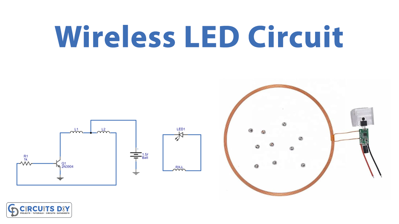
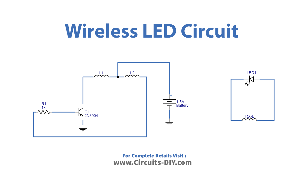
Circuit Diagram
Working Explanation
This circuit involves two circuits:
- A transmitter circuit
- A receiver circuit
A Transmitter Circuit
The TX-Coil is constructed from 30 standard-gauge enamelled copper wire with a 6CM diameter. NPN transistor 2N3904 is utilized for low-power switching. And the transistor Q1 creates a high-frequency switching pulse from the bias-applied voltage to the transmitter coil’s centre tap terminal. As a result, the TX-coil is energized, producing an alternating magnetic field.
A Reciever Circuit
The same type of enamelled copper wire used for the TX-coil, with a 6CM diameter and 30 turns, is used to make the Rx-coil. As a result of inductive coupling caused by magnetic flux being received nearby by the Rx-Coil, the LED begins to glow. The distance between this receiver circuit and the transmitter circuit is around three inches.
Application and Uses
- Wireless power generation
- Automation systems, etc