In this tutorial, we are going to make an “LED as a Light detector”. Ever wonder what’s behind your smartphone and tablets that allow for auto-screen brightness adjustments? Yes, it’s an ambient light detector. It measures the ambient light level of your surroundings and determines the suitable brightness of your screen. A light detector is a photoelectric device that converts light energy (photons) detected to electrical energy (electrons). And mostly we use different light sensor elements to see the light beam, here for a change we can use an LED device to detect light signals. We design a simple circuit by utilizing Light Emitting Diode as a light sensor.
Hardware Required
| S.no | Component | Value | Qty |
|---|---|---|---|
| 1. | IC | TL071 | 1 |
| 2. | Transistor | BC547, BC337 | 1,1 |
| 3. | Resistor | 10MΩ,470KΩ,3.3KΩ,1KΩ,330Ω | 1,1,1,2,1 |
| 4. | Variable Resistor | 10KΩ | 1 |
| 5. | Connecting Wires | – | – |
| 6. | LED | – | 1 |
| 7. | Battery | 9V | 1 |
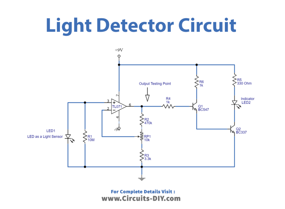
Circuit Diagram
Working Explanation
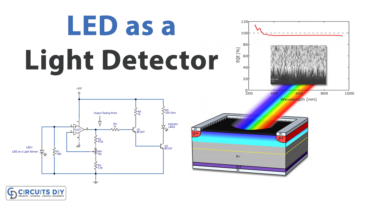
Color Spectrum
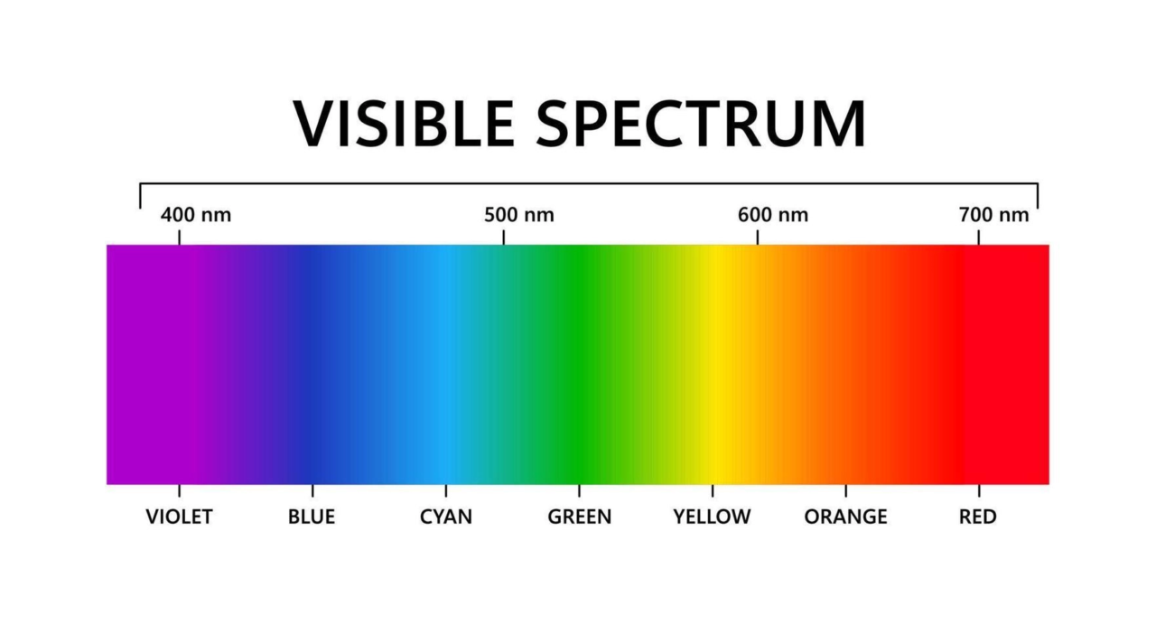
To detect a large spectrum of light signals from 400nm to 1,000nm normally we use a photodiode. But here LEDs are designed to emit a particular wavelength of light by using semiconductors, therefore these are very narrow at sensing light signals. However, a LED can both emit and detect lights. The brightness of the light observed from an LED depends on the power emitted by the LED and on the relative sensitivity of the eye at the emitted wavelength.
Now to design color-specific LEDs different semiconductor materials are mixed together. Like RED LEDs are made from (AlGaAs) Aluminum Gallium Arsenide. Green and Blue LEDs are made from (GaN) Gallium Nitride. Here semiconductor light sensing characteristics may vary.
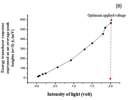
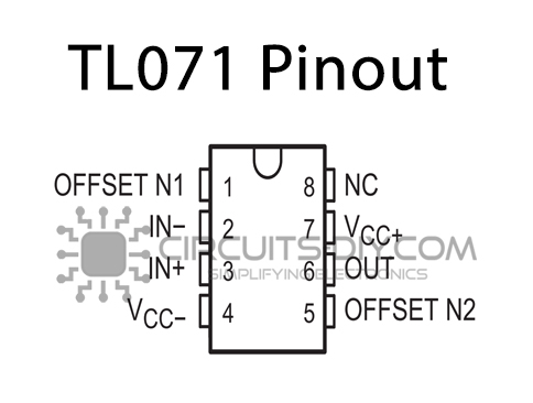
Here we have used a 5mm transparent RED LED as a light sensor and a 5mm white LED2 as an indicator. Here to amplify the detected signal JFET input operational amplifier TL071 is used. This amplifier needs a dual power source (+9V to -9V) to operate. Now BC547 and BC337 NPN transistors drive the indicator LED. When the sensor LED in the dark output of TL071 changes to a high state, this turns ON Q1 and Q2 then the indicator is turned ON. When the light falls on LED1, the output state of TL071 becomes low, and the Q1 and Q2 transistors are turned off. Since there is no bias to the indicator and thus LED2 is turned off. We can get varying output voltage depending on the intensity of the light signal.
Output Response
Pinout of TL071
Applications
- Consumer electronics
- Automobiles
- Agricultural Usages
- In security applications