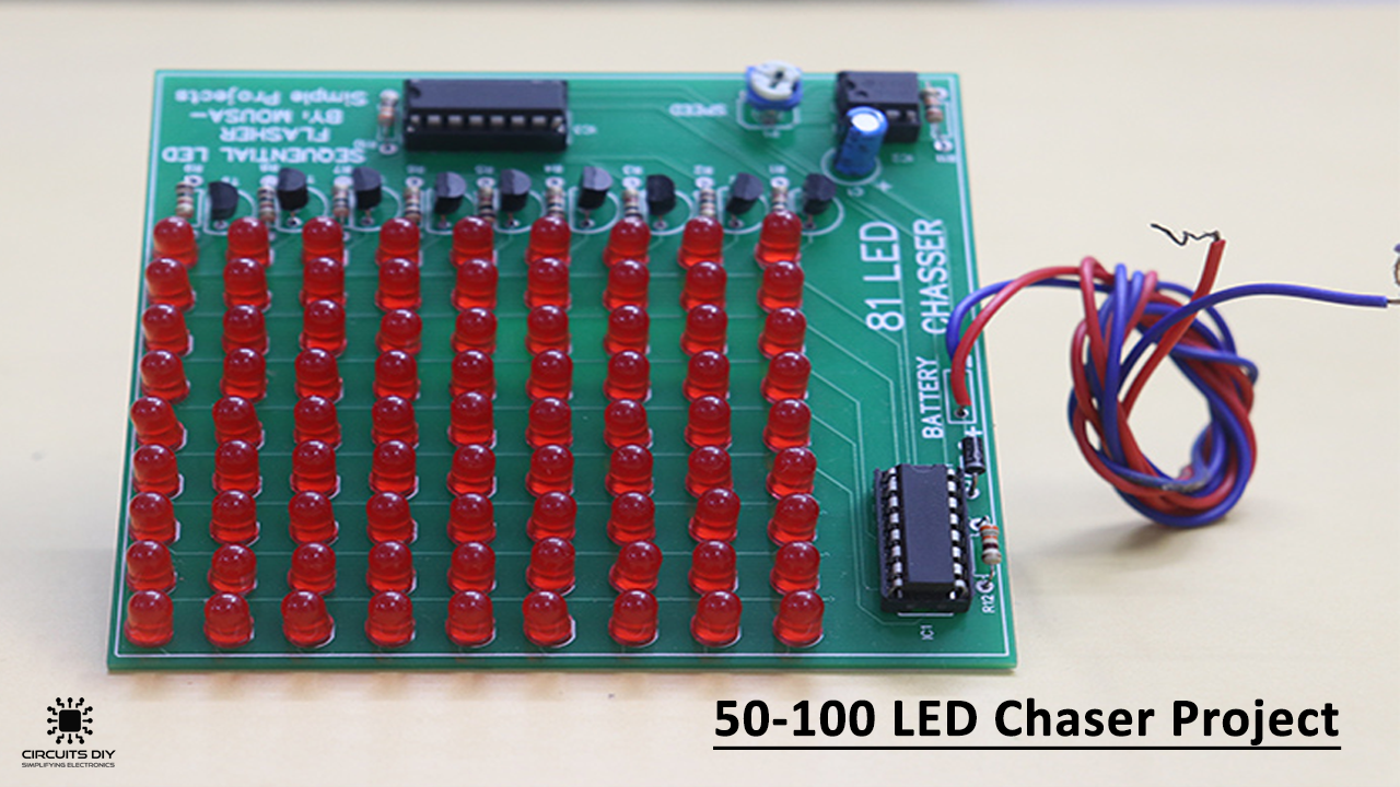
Well, Are you searching for around 100 LEDs chasers or sequencer circuits? Then this project will work commendably for you!. The circuit is easy to assemble and comprehend. The Circuit is utilizing six 4017 decade counter ICs and one 555 timer IC. This circuit will illuminate 50 LEDs individually or in the grouping.
The succession will work first it will illuminate individually. All LEDs are linked with the primary output of each 4017 ICs which is “Q0”. At that point, it will illuminate all LEDs individually associated with the second yield of each of the 4017 IC which is Q1.
Hardware Components
The following components are required to make LED Chaser Circuit
| S.no | Components | Value | Qty |
|---|---|---|---|
| 1. | IC | NE555 Timer | 1 |
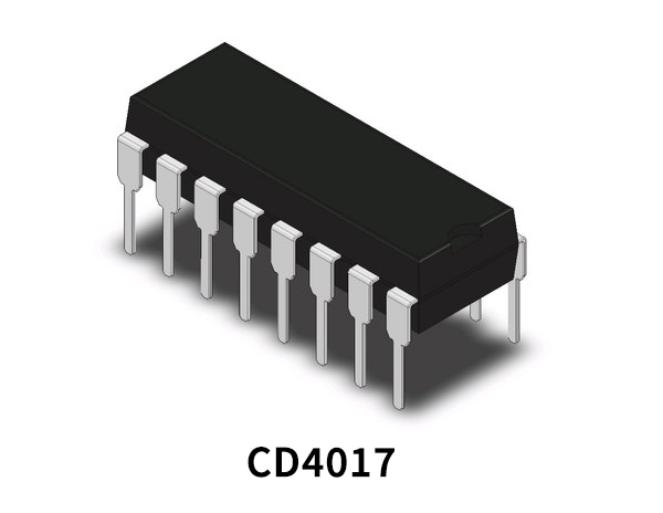
| 2. | Decade Counter Divider IC | CD4017 | 6 |
| 3. | LEDs | – | 50 |
| 4. | Variable resistor | 100K | 1 |
| 5. | Resistor | 390R, 2.7K, 1K | 5, 1, 1 |
| 6. | Electrolytic Capacitor | 10µF | 1 |
| 7. | Ceramic Capacitor | 0.01µF | 1 |
| 8. | Battery | 5V – 12V | 1 |
NE555 Pinout

For a detailed description of pinout, dimension features, and specifications download the datasheet of 555 Timer
CD4017 Pinout
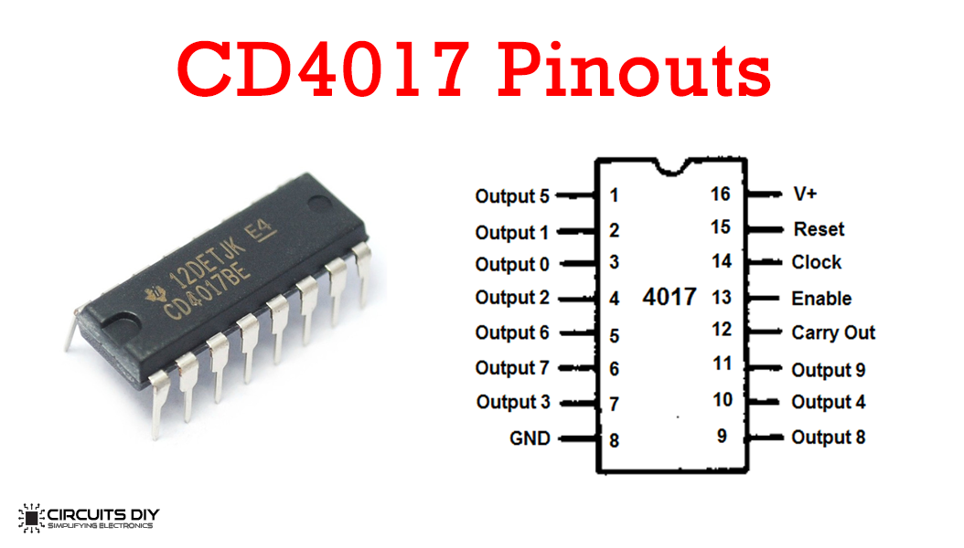
For a detailed description of pinout, dimension features, and specifications download the datasheet of CD4017
LED Chaser Circuit

Working Explanation
The circuit is utilizing 50 LEDs however you can expand the number of LEDs to 60, 70, 80, 90, or 100 by just including a 4017 IC for every ten LEDs, and interface a yield of the IC2 to its pin14. For instance, on the off chance that you need 60 LED chasers, at that point essentially include one increasingly 4017 decade counter IC with the same associations and detach the pin1 of the IC2 from IC2 pin15 and interface the IC2 pin1 with the new included 4017 pin14. After that associate pin5 of the IC2 to IC2 pin15.
You can likewise decrease the number of LEDs to 40, 30, or 20 by basically expelling each 4017 IC and interfacing its output to pin 15 of the IC2. For instance, on the off chance that you need 40 LED chasers, at that point just expel the IC7 and interface the pin10 of the IC2 to pin15 of the IC2 and evacuate the association of pin1. The circuit can likewise be utilized for different purposes like 50 to 100 separate pulse generators and so forth. The working voltage of the circuit is 5V to 12V DC.
Applications and Uses
The alleged chaser or sequencer is one of the most mainstream kinds of LED-driving circuits and is generally utilized in the following:
- Display in small discos
- Advertising Displays
- In running-light ‘rope’ and so forth