Automatic emergency products like tube lights and bulbs are becoming very popular as these become elegant solutions for situations where you can expect the AC power to go down sometimes from a few minutes to a few hours and you do not want the place/area to go into total darkness. Emergency lights are very crucial in some situations, the traditional emergency light uses a fluorescent tube as a light source.
Therefore it provides light up to a maximum of 2 hours to 3 hours. When we use white LEDs instead of fluorescent tubes it will give light for up to 7 hours approximately. So an automatic LED emergency Light circuit is designed to turn ON when there is no adequate lighting or if the power supply is cut-off. Earlier fluorescent lights were used to build such circuits. But the use of LEDs has proven to provide adequate lighting for a longer period before draining the battery. Here we construct a circuit with easily available components. This full automatic emergency tube light circuit consists of two stages.
- Battery charger circuit
- 20 Watts tube light driver circuit
Hardware Required
| S.no | Component | Value | Qty |
|---|---|---|---|
| 1. | Step Down Transformer Center Tapped | 9-0-9 V | 1 |
| 2. | Step Down Transformer | 9-0-9 V | 1 |
| 3. | Transistor | BC547 | 1 |
| 4. | Voltage Regulator IC | LM317 | 1 |
| 5. | Tube Light | 20W | 1 |
| 6. | Transistor | SL100 | 1 |
| 7. | Transistor | 2N3055, MJE3055 | 1 |
| 8. | Diode | 1N4007 | 3 |
| 9. | Zener Diode | 6.8V,0.5W | 1 |
| 10. | Resistor | 1KΩ,4.7KΩ,10KΩ,100Ω,150Ω | 2,2,1,1,1 |
| 11. | Variable Resistor | 1KΩ | 1 |
| 12. | Capacitor | 0.01uF,0.1uF,6.8uF/25V | 1,1,1 |
| 13. | Connecting Wires | – | – |
| 14. | Battery | 6V, 4Ah | 1 |
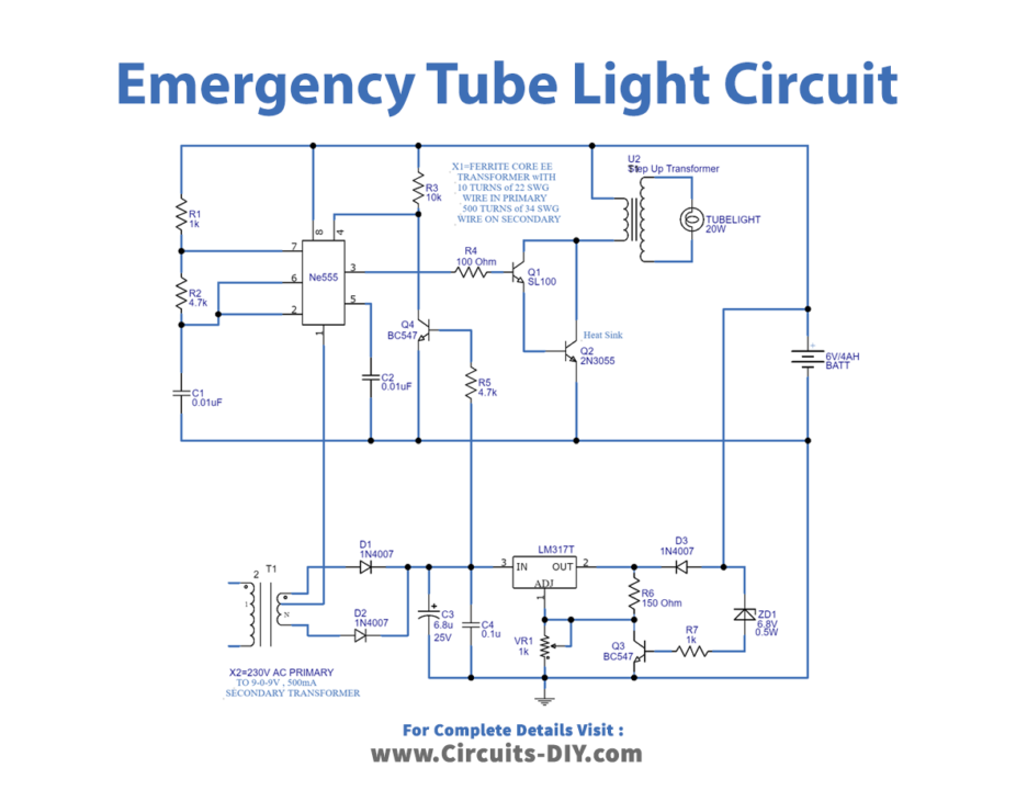
Circuit Diagram
Working Explanation
As we can see, this circuit has two stages that are Battery charger circuit and 20 Watts tube light driver circuit. Here the battery charger circuit is constructed by using a step-down transformer (9-0-9 V) center-tapped, which steps down the input voltage. Then two 1N4007 diodes are placed to act as full-wave rectifiers and rectify the step-downed AC supply from the transformer. Further, this rectified DC is filtered by capacitors and regulated by variable voltage regulator IC LM317. Then this regulated constant DC supply is given to the 6-volt 4Ah battery. Now the T4 transistor (BC547) splits the tube light driver circuit from the charger circuit when the power supply is present.
20 Watts tube light driver circuit
As we can see, this is based on timer IC555 and step-up transformer X1. This step-up transformer’s (X1) primary winding is constructed with 10 turns of 22SWG and 500 turns of 34SWG wire on the secondary. Here the 20W tube light connected at the secondary of X1, X1 transformer primary driven by pulse output from timer IC 555. Now R1, R2, and C1 timing components are used to decide the pulse duration of IC555. The calculation formula is given as
[F = 1/T = 1.44/(R1 + 2R2).C1]
Applications
- The circuit is useful where there are load-shedding issues.
- Can be used in street lights.
- Also, can be employed to avoid sudden power failures at workplaces.