A flip flop circuit, here, flashes two sets of LEDs ON ad OFF in a flip flop manner. the circuit includes IC NE555 for the time triggering switching. Also, the circuit uses both the NPN and PNP transistors to achieve the required transition of lighting of LEDs.

Hardware Components
The following components are required to make Flip Flop flashing Circuit
| S.no | Component | Value | Qty |
|---|---|---|---|
| 1. | IC | NE555 Timer | 1 |
| 2. | Transistor | BD139, BD140 | 1 |
| 3. | Electrolytic Capacitor | 10µF | 1 |
| 4. | Battery | 12V | 1 |
| 5. | LEDs | – | 36 |
| 6. | Variable Resistor | 100KΩ | 2 |
| 7. | Resistor | 62Ω, 1KΩ, 4.7KΩ | 12, 2, 2 |
| 8. | Ceramic Capacitor | 10nF | 1 |
NE555 IC Pinout

For a detailed description of pinout, dimension features, and specifications download the datasheet of 555 Timer
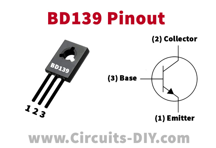
BD139 Pinout

For a detailed description of pinout, dimension features, and specifications download the datasheet of BD139
Flip Flop flashing Circuit

Working Explanation
IC NE555 is a timer IC with which the ON and OFF time duration of the LEDs is achievable. Since the output of the NE555 timer IC is just 200mA, therefore, the IC is capable of driving only a few LEDs. Hence, two powerful transistors help increase the number of LEDs connected in the circuit. The transistors used in the circuit are NPN BD139 and PNP transistor BD140 which are able to drive a maximum of 140 LEDs altogether. This is because, the output current of both the transistor is 1.5A, enough to drive more than 120 LEDs. While connecting the LEDs with the transistors, it is necessary to connect a current limiting resistor as well.
If more than 18 LEDs are used in the circuit then a heatsink is also required with each of the transistors in order to prevent them from burning. The two 100KΩ variable resistors adjust the switching rate of the two sets of LEDs, respectively. Furthermore, the operating voltage of the circuit is 12V.


