Introduction
In this tutorial, we are going to make a “fluorescent lamp driver.” The drivers for fluorescent lights are difficult to design because they must find a balance between running efficiency and the ability to start the bulb. The demands conflict with one another. Therefore, we attempt to create a circuit that will fulfill both requirements.
A fluorescent lamp, often known as a fluorescent tube, is a low-pressure mercury-vapor gas-discharge lamp that emits visible light using the fluorescence principle.
What is Fluorescent Lamp Driver?
The fluorescent light driver is a device that controls the power of your fluorescent lamps. It resembles a ballast used in fluorescent lighting systems. In short, the driver ensures that your lighting operates safely and efficiently.
Hardware Required
| S.no | Component | Value | Qty |
|---|---|---|---|
| 1. | step-down transformer | 0-3V | 1 |
| 2. | IC | NE555 Timer | 1 |
| 3. | Transistor | BD243C | 1 |
| 4. | Lamp | – | 1 |
| 5. | Potentiometer | 4.7K | 2 |
| 6. | Capacitor | 100nF | 1 |
| 7. | Resistor | 1.5K | 2 |
| 8. | 2-Pin Connector | – | 1 |
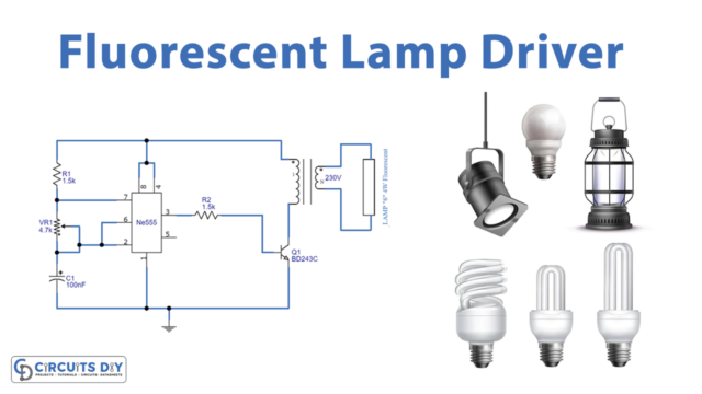
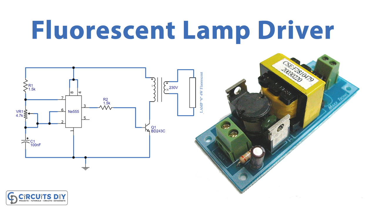
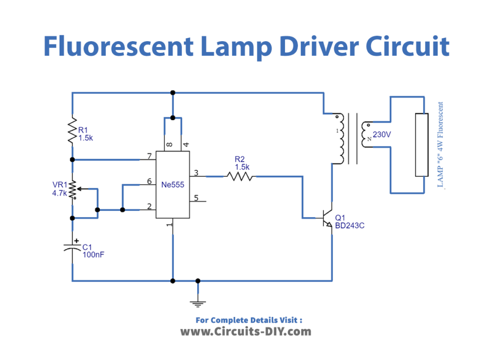
Circuit Diagram
Working Explanation
The timer IC555 is used in this circuit as a pulse driver for fluorescent lights. Timing resistor R1, potentiometer VR1, and capacitor C1 are used to set the timer IC555 as a multi-vibrator. Pin 3 of an is used to generate the switching pulse for the output, and the VR1 value controls how long the pulse lasts. The BD243C transistor serves as a switching transistor, driving a 4-watt fluorescent bulb using a step-down converter.
The lamp is connected to the primary winding, the switching circuit to the secondary winding, and by the switching pulse, the secondary winding produces an EMF that induces the primary winding, producing a high voltage at the primary that is sufficient to run a 4-watt fluorescent bulb.
Application and Uses
- Residences, buildings, and hotels everywhere where fluorescent lamps are used
- In streetlight driving projects
- In general, lighting projects.