Introduction
Interfacing a Light-dependent resistor (LDR) with an Arduino microcontroller to control an LED based on the ambient light level is a simple yet powerful way to create projects that can adapt to changes in the environment. By using an LDR sensor, which is sensitive to changes in light intensity, and an Arduino microcontroller, which can process the sensor’s data and control an LED, you can create projects that can react to changes in ambient light, such as street lighting, automatic room lighting, and energy-efficient lighting systems.
A light-dependent resistor (LDR) is a type of resistor whose resistance changes based on the intensity of the light that falls on it. LDRs are also known as photo resistors or photoconductors. They are made of a semiconductor material, typically cadmium sulfide (CdS), that changes its conductivity depending on the amount of light that falls on it. When the light is intense, the resistance of the LDR decreases, and when it is dim, the resistance of the LDR increases
Hardware Components
You will require the following hardware for Light Sensor Arduino Circuit.
| S.no | Component | Value | Qty |
|---|---|---|---|
| 1. | Arduino UNO | – | 1 |
| 2. | USB Cable Type A to B | – | 1 |
| 3. | Light Sensor | – | 1 |
| 4. | Power Adapter for Arduino | 9V | 1 |
| 5. | LED | – | 1 |
| 6. | Resistor | 10KΩ,220Ω | 1,1 |
| 7. | Breadboard | – | 1 |
| 8. | Jumper Wires | – | 1 |
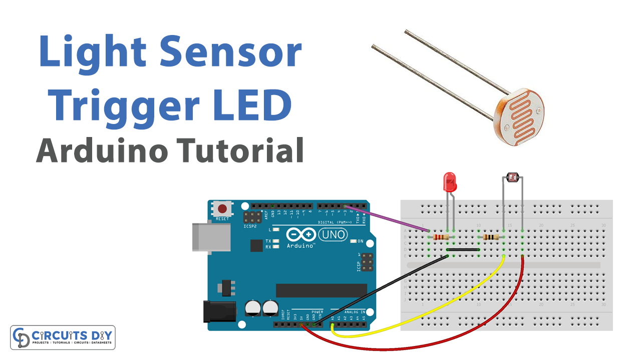
Light Sensor LED with Arduino
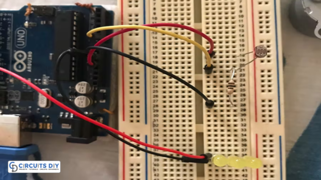
- Connect the LDR sensor to the Arduino UNO microcontroller using the VCC, GND, and A0 pins.
- In the Arduino IDE, include the necessary libraries for the LDR sensor:
#include <Arduino.h>
- In the setup() function, initialize the serial communication and the pin mode for the LED:
Serial.begin(9600);
pinMode(ledPin, OUTPUT);
- In the loop() function, read the sensor’s output value using the analogRead() function and store it in a variable:
int sensorValue = analogRead(ldrPin);
- Use an if statement to check if the sensorValue is above or below a certain threshold value, and turn the LED on or off accordingly.
if(sensorValue > thresholdValue){
    digitalWrite(ledPin, HIGH);
    Serial.println("Light level is high");
}else{
    digitalWrite(ledPin, LOW);
    Serial.println("Light level is low");
}
- You can adjust the threshold value to set the level of light at which you want the LED to turn on or off.
- Upload the code to the Arduino UNO and open the serial monitor to see the sensor’s output values.
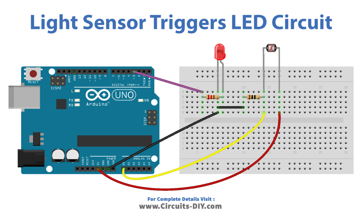
Schematic
Make connections according to the circuit diagram given below.
Installing Arduino IDE
First, you need to install Arduino IDE Software from its official website Arduino. Here is a simple step-by-step guide on “How to install Arduino IDE“.
Code
Now copy the following code and upload it to Arduino IDE Software.
const int LIGHT_SENSOR_PIN = A0; // Arduino pin connected to light sensor's  pin
const int LED_PIN          = 3;  // Arduino pin connected to LED's pin
const int ANALOG_THRESHOLD = 500;

// variables will change:
int analogValue;

void setup() {
  pinMode(LED_PIN, OUTPUT); // set arduino pin to output mode
}

void loop() {
  analogValue = analogRead(LIGHT_SENSOR_PIN); // read the input on analog pin

  if(analogValue < ANALOG_THRESHOLD)
    digitalWrite(LED_PIN, HIGH); // turn on LED
  else
    digitalWrite(LED_PIN, LOW);  // turn off LED
}
Working Explanation
The setup() function of the LDR analog threshold-controlled LED code is used to initialize the necessary settings for the program. This includes initializing the serial communication with the computer and setting the pin mode for the LED pin.
The loop() function of the LDR analog threshold-controlled LED code is used to execute the main code logic. This includes reading the sensor’s output value, comparing it to a pre-set threshold value, and turning the LED on or off accordingly. The status of the light level and the state of the LED is posted on the serial monitor, allowing real-time observation and adjustments to the system. The loop function will repeat indefinitely, allowing the Arduino to continuously check the light level and adjust the LED accordingly.
Applications
- Automation
- Safety
- Display
- Photography
- Power saving
- Robotics.
Conclusion.
We hope you have found this Light Sensor Arduino Circuit very useful. If you feel any difficulty in making it feel free to ask anything in the comment section.