Introduction
Humans strive daily towards an automated society. We like avoiding time-wasting activities that might otherwise prevent us from completing important jobs. Take street lights as an example; to manually switch them on, someone must do so every day. However, if we automate using an automatic brightness sensor then it will sense the darkness and switch on automatically.
So, to make this Automatic Brightness Sensor, we’re utilizing LDR since its semiconductor construction makes them light-sensitive. This circuit is useful for a wide range of purposes and is simple to construct and run.
What is Brightness Sensor?
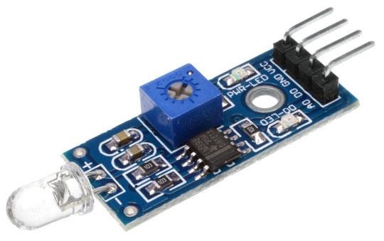
A brightness sensor is a photoelectric device that transforms the detected light energy (photons) into electrical energy (electrons). It comes in a variety of forms and has a wide range of uses. Photoresistors, which are sometimes referred to as Light-Dependent Resistors (LDRs), are the most popular form of brightness sensor. Photoresistors examine the relative light levels and determine whether a light is on or off.
Hardware Components
You will require the following hardware for the Automatic Brightness Sensor.
| S.no | Component | Value | Qty |
|---|---|---|---|
| 1. | Arduino UNO | – | 1 |
| 2. | Photo Resistor | – | 1 |
| 3. | Relay Module | – | 1 |
| 4. | LED | – | 1 |
| 5. | Resistor | 221Ω | 1 |
| 6. | Breadboard | – | 1 |
| 7. | Jumper Wires | – | 1 |
Steps for Making Automatic Brightness Sensor
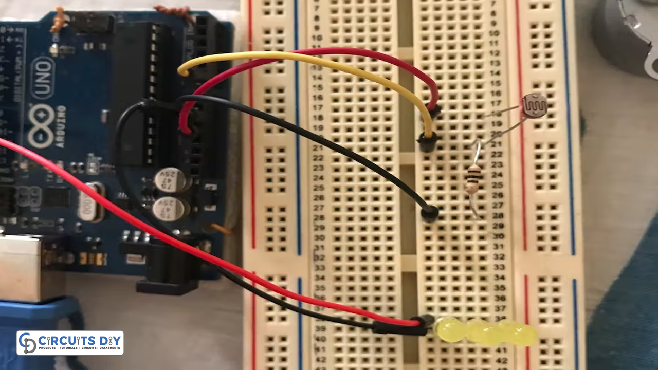
This automatic brightness sensor requires a single resistor, wires, and breadboard with Arduino and LDR. Once you get those components; follow the given steps:
Schematic
Make connections according to the circuit diagram given below.
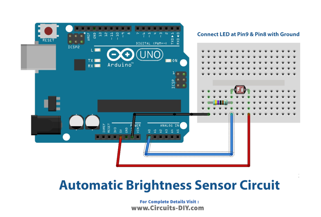
Wiring / Connections
| Arduino | Photo Resistor |
|---|---|
| 5V | 1st Pin |
| GND | 2nd Pin with R1 |
| A0 | 2nd Pin |
Installing Arduino IDE
First, you need to install Arduino IDE Software from its official website Arduino. Here is a simple step-by-step guide on “How to install Arduino IDE“.
Code
Now copy the following code and upload it to Arduino IDE Software.
//OUKHEIR Achraf
const int LumPin = A0;    // select the input pin for Senosr
const int RidPin1 = 9;      // select the pin for Rideaux
const int RidPin2 = 8;      // select the pin for Rideaux
int LumValue = 0;  // variable to store the value coming from the sensor
int SiLum =0 ; //Etat rideau 0
void setup() {
  // declare the ledPin as an OUTPUT:
  pinMode(RidPin1, OUTPUT);
  pinMode(LumPin, INPUT);
  Serial.begin(9600);
}

void loop() {
 Serial.print("Luminoste value = ");
Serial.println(ReadLum());

SiLum= LightDark();
if(SiLum==1){
   Rideaux1(1);
}else {
  Rideaux1(0);
}

delay(1000);
}


//fonction de Luminosite read
int ReadLum(){
LumValue =analogRead(LumPin);
delay(100);
  return  LumValue;
}

//fonction de check Luminosite
int LightDark(){
 //check ifDark or light
  if ( LumValue  < 28) {
    // turn  on:
    digitalWrite(RidPin1, HIGH);
    return 1;
  } else  if ( LumValue  >33){
    // turn  off:
    digitalWrite(RidPin1, LOW);

  return 0;
  }

}

//fonction de Rideau
int Rideaux1(int act){
  if(act==1){
    digitalWrite(RidPin1, HIGH);
  return 1;
  }else{
  digitalWrite(RidPin1, LOW);
  return 0;
  }
  }
Let’s Test It
It’s now time to test the circuit. So, power up your Arduino. The LEDs in this auto brightness sensor will automatically switch on according to the brightness values defined in the code.
Working Explanation
Look into the coding for a working explanation:
- We first have a name and defined the pins of Arduino that are being used in the circuit. We also define the variable LumValue to store the value coming from the sensor.
- In the void setup, we declare the status of two defined pins as the input and output. We then initialize the serial monitor.
- In the void loop, we use different conditions to sense the brightness and provide output accordingly.
The resistance of LDR is proportional to the intensity or brightness of light incident on it, and the connection is inverse. This implies that as the light intensity changes, the LDR’s resistance changes, So, when the resistance of the photoresistor changes, the voltage divider’s output voltage changes.
Applications
- Street lights
- Light failure alarm circuits
- Light meters; etc
Conclusion
We hope you have found this Automatic Brightness Sensor Circuit very useful. If you feel any difficulty in making it feel free to ask anything in the comment section.