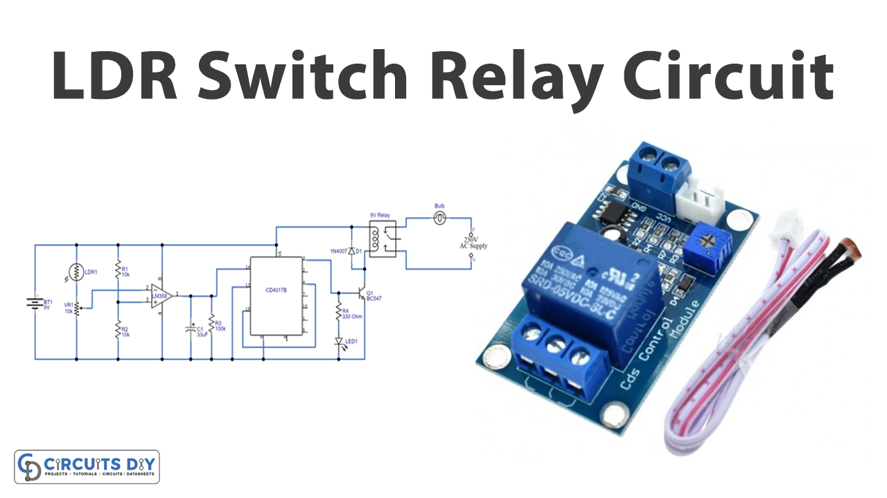
In this tutorial, we are going to make an “LDR Switch Relay Circuit”.
Most of the time the process of appliance controlling may cause wastage of power due to the carelessness of human beings or unusual circumstances and sometimes it is also very risky, as the controlling of lights and home appliances is generally operated and maintained manually. Let’s say the bathroom switch, what if we use our wet fingers to turn it on or off it may give an electric shock. So, it would be dangerous, to avoid these situations we can use the simple LDR switch relay circuit. An LDR or a photoresistor is a device that is made up of high resistance semiconductor material, it is a type of variable resistor that increases its resistance when the light decreases and its resistance decreases when light increases. Here LDR acts as a shadow sensing device and makes turns ON or OFF the Relay whenever it detects the shadow and keeps the relay in either ON or OFF condition until the next detection of shadow. We can swipe our hands above the LDR to turn ON/OFF the electrical appliances. It means this LDR switch relay circuit eliminates physical contact with an electrical appliance.
Hardware Required
| S.no | Component | Value | Qty |
|---|---|---|---|
| 1. | Decade Counter IC | CD4017 | 1 |
| 2. | Dual Operational Amplifier IC | LM358 | 1 |
| 3. | Relay Module | 9V | 1 |
| 4. | LDR (Light Dependent Resistor) | – | 1 |
| 5. | Variable Resistor | 10KΩ | 1 |
| 6. | Resistor | 10K, 100K, 330Ω | 2, 1, 1 |
| 7. | Capacitor | 33uF | 1 |
| 8. | Diode | 1N4007 | 1 |
| 9. | LED | – | 1 |
| 10. | NPN Transistor | BC547 | 1 |
| 11. | AC Bulb | 230V | 1 |
| 12. | Connecting Wires | – | – |
| 13. | Battery/ DC power supply | 9V, 9V | 1 |
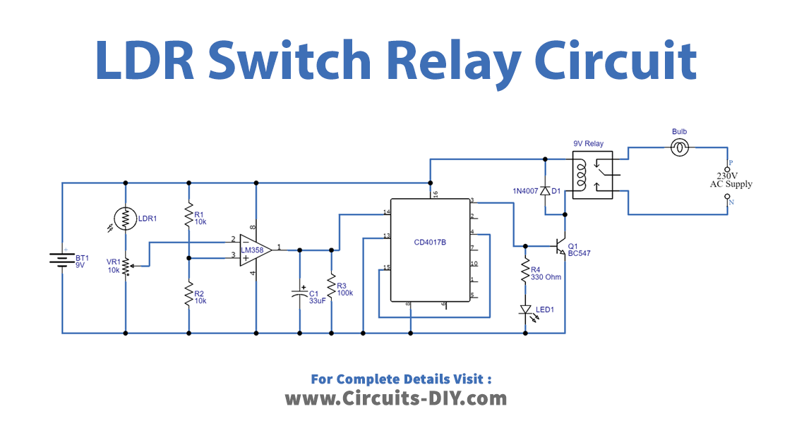
Circuit Diagram
Working Explanation
As we can see this LDR switch relay circuit has two stages to drive the relay, the first one is the sensor-operational amplifier and another one is a decade counter. Here LDR is connected with Variable resistor VR1 and a variable terminal connected with operational amplifier inverting input, we can adjust the sensitivity level of LDR by changing the value of VR1. Voltage divider circuit which has R1 and R2 resistors are made to balance the operation of a non-inverting input of amplifier LM358. Then the output of operational amplifier one is obtained from pin 1 and fed into the clock input of the decade counter. Here C1 and R3 are used to stabilize the output from the operational amplifier. Now the IC CD4017 is placed to count the clock and gives 10 outputs from Q0 to Q9. Here output relay is connected with Q0 through switching transistor BC547. And an LED1 is connected which indicates the ON condition of the relay.
As LDR is a type of variable resistor that increases its resistance when the light decreases and its resistance decreases when light increases. It means in a dark place or when no light falls on LDR, the resistance of it is very HIGH and in Sufficient light, the resistance of LDR is very LOW. Here electrical appliance (bulb) is connected between N/O (Normally Open) and Common pin with a relay. When any human or object approaches the LDR, it detects the shadow then the relay gets supply and turns ON the bulb, and stays in the same condition until another shadow detection by the LDR. If you’re using this circuit as a permanent setup then you have to use Step down transformer and rectifier-regulator to have a 9V DC power supply.
Applications
Can be used to control lights and other electronic appliances at home, offices, malls, and hospitals.