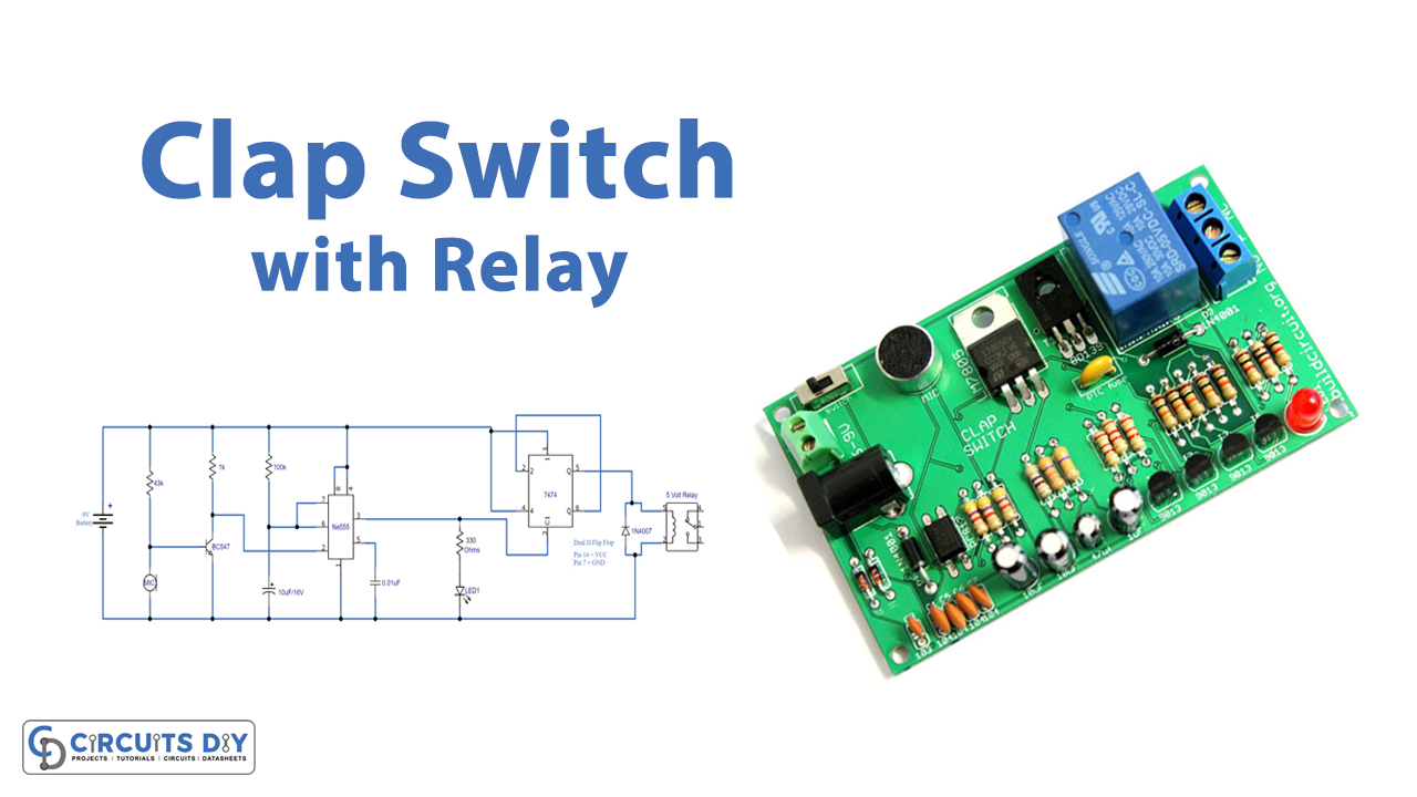
In this tutorial, we are going to make a “Clap Switch Circuit with Relay”.
Let’s say you want to turn ON and turn OFF any electric appliance without reaching a physical switch then you need a simple Clap Switch type circuit. A clap switch is a circuit that operates through a clap sound or similar to that sound. This switch activates once or twice clapped & deactivates when again clapped once based on the design of the circuit. Here we design a simple circuit with timer IC 555, dual D flip flop IC 7474, and an electromagnetic relay. When you clap or make a louder sound to trigger the circuit, it will turn ON or turn OFF the load connected with the relay. Here a simple condenser mic acts as a sensor in this circuit. The basic concept of this clap switch is that the microphone receives the clap sound & generates a small signal to control a light, fan, and TV through clapping.
Hardware Required
| S.no | Component | Value | Qty |
|---|---|---|---|
| 1. | IC dual D flip flop | 7474 | 1 |
| 2. | IC | NE555 Timer | 1 |
| 3. | Relay (SPDT) | 5V | 1 |
| 4. | Transistor NPN | BC547 | 1 |
| 5. | Condenser Mic | – | 1 |
| 6. | LED | – | 1 |
| 7. | Diode | 1N4007 | 1 |
| 8. | Resistor | 43KΩ, 1KΩ, 100KΩ, 330Ω | 1,1,1,1 |
| 9. | Capacitor | 10μF, 0.01μF | 1,1 |
| 10. | Connecting Wires | – | – |
| 11. | Battery | 9V | 1 |
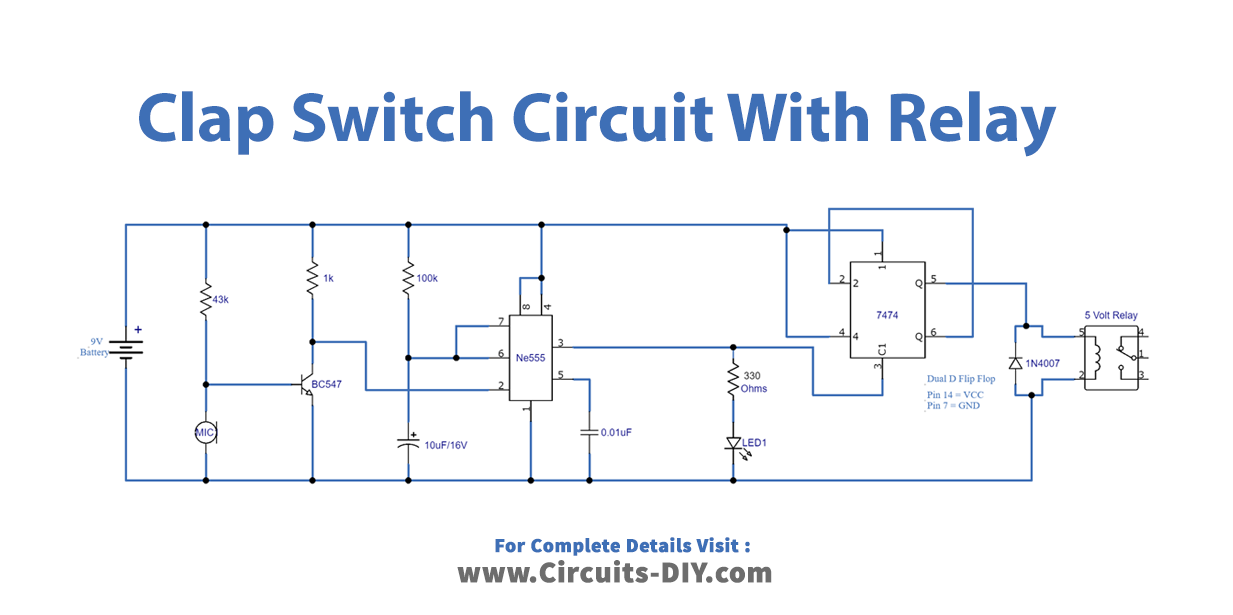
Circuit Diagram
Condenser Mic
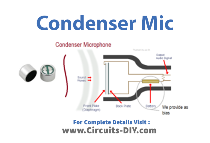
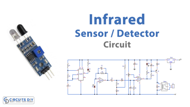
Condenser microphones are one of the most popular mics, they will provide a wider frequency response range than their dynamic microphone cousins, but will have a lower input sensitivity. All condenser microphones are working in the same way and are available in different sizes. A condenser mic will have a fixed backplate and a movable front plate which is the diaphragm and is separated by an air insulator. When the sound wave hits the front plate then it moves according to the sound wave and makes a different capacitance level this signal can be used as an electric audio signal. To produce an electric audio signal the condenser mic requires bias and an amplifier.
Working Explanation
As we can see circuit consists of three stages the sound detector stage, the second stage is a timer then the third stage is a D flip flop. The sound detector stage is made by a condenser mic and transistor BC 547 as a level shifter. The timer stage has IC 555, this IC is employed as a monostable multivibrator which will produce one timing pulse depending on timing resistor R3 and timing capacitor C1. Here when it receives trigger input from the sound detector stage. The output pulse from the timer IC is directly fed into the third stage which is the D flip flop. Now the Input pulse makes the D flip flop into either SET or RESET position. The relay is connected at the Q output of D flip flop gets energized and turns ON load during the set condition and turns OFF load during the Reset condition.
Applications
A clap switch is used to switch ON/OFF different electrical appliances like the following.
- Fan
- Light
- TV
- Motor
- AC
- This system is very useful for mobility-impaired persons and elders