Introduction
A voltage doubler is an electronic multiplier circuit that produces a DC output that has an amplitude double the amplitude of an AC input voltage. In 1932 two men Walton and Walton created an 800 supply for an accelerator, since then voltage multipliers, and doubles have been used where the circuits need high voltages with low current. There are two types of doubler circuits, a half-wave doubler, and a full-wave doubler. The doubler circuits eradicate the use of a high-voltage transformer, also the voltage can be increased greatly by cascading multiple stages in the circuit.
The circuit uses the 555 timer IC connected as a stable multivibrator to supply the input to the charge pump To maintain the good regulation of output voltage, the load current should be less.
Hardware Required
| S.no | Component | Value | Qty |
|---|---|---|---|
| 1. | Veroboard | – | 1 |
| 2. | Resistor | 100 ohms, 10K | 2, 1 |
| 3. | IC | NE555 Timer | 1 |
| 4. | Capacitor | 0.0082uF, 10uF, 100uF | 2, 1, 1 |
| 5. | Diode | 1N4007 | 2 |
| 6. | Transistor | BC107, BC177 | 1, 1 |
| 7. | Power supply | 12V | 1 |
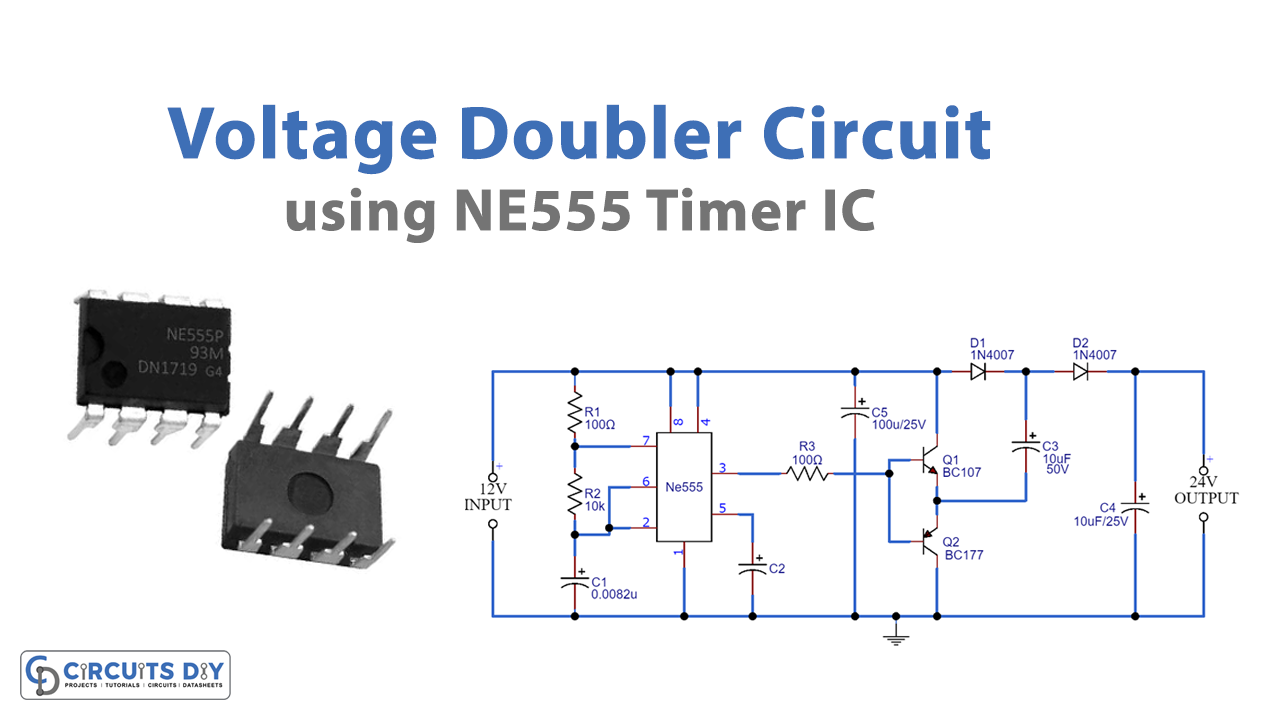
Circuit Diagram
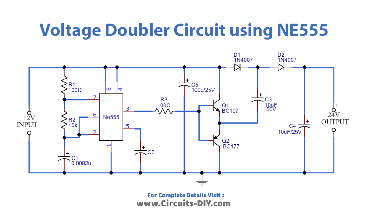
Working Explanation
IC NE555 operates at 90KHz in a stable multivibrator mode. Both the transistors are shorted together and output from the IC pin 3 is given to the transistor. At low output transistor (Q1) will be OFF and the transistor (Q2) will be ON. When the output signal from Pin 3 is high transistor Q1 will be ON and transistor Q2 will be OFF. And at the output, we get twice the input voltage
Application and Uses
- It can be used in X-Ray systems
- It can be utilized in radar devices
- It exists in