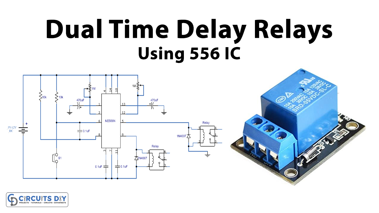
In this tutorial, we are making a project of dual-time delay relays using 556 IC. The 556 is a dual timer IC that has two 555 timers in a single 14 pin package. Since this IC has two timers in it so it can be used for both pulse generation and oscillations simultaneously. Each timer has its own trigger, threshold, control, discharge, reset, etc. Two relay switches are operated with this circuit, both of them can be adjusted for different time periods.
Hardware Components
The following components are required to make Dual Time Delay Circuit
| S.no | Component | Value | Quantity |
|---|---|---|---|
| 1 | Input supply DC | 5-12V | 1 |
| 2 | IC | NE556 | 1 |
| 3 | Switch | 1 | |
| 4 | Resistor | 10KΩ | 2 |
| 5 | Electrolytic Capacitor | 470µF | 2 |
| 6 | Ceramic Capacitor | 0.1µF | 3 |
| 7 | Diode | 1N4007 | 2 |
| 8 | Relay | 2 | |
| 9 | Variable Resistor | 1M | 2 |
NE556 IC Pinout
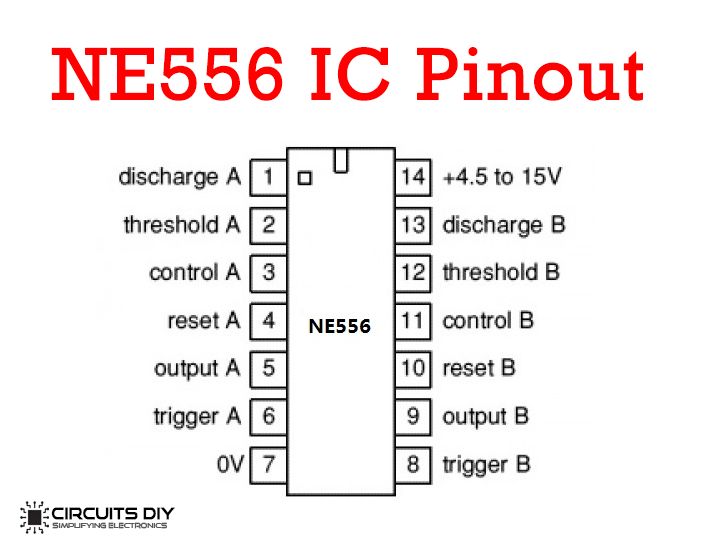
For a detailed description of pinout, dimension features, and specifications download the datasheet of NE556 IC
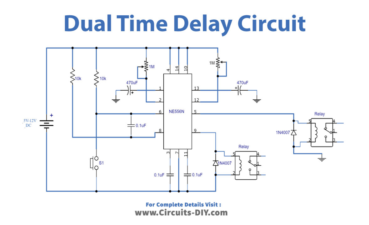
Dual Time Delay Circuit
Working Explanation
The operating voltage of this circuit is 5 to 12 volts DC. The main component of this circuit is the 556 IC. When the push button S1 is pressed it will activate both the timers in the 556 IC. Now, these two timers will be responsible for operating each relay switch. You can connect any appliance with the relay switches to operate or switch on & off with this circuit. The time period of these timers depends on the 470uF capacitor and 1M variable resistor. The 470uF capacitor will give a time delay of 8 to 10 minutes max. if you use a 1000uF capacitor it will provide an increased time delay of approx. 20 minutes. So the time period can be further increased by increasing the value of this capacitor. Make sure to use the relay switch having the same voltage as the operating voltage
Applications and Uses
- Delay applications
- Timer circuits
- Operating appliances like lamps, fans, bulbs, etc.