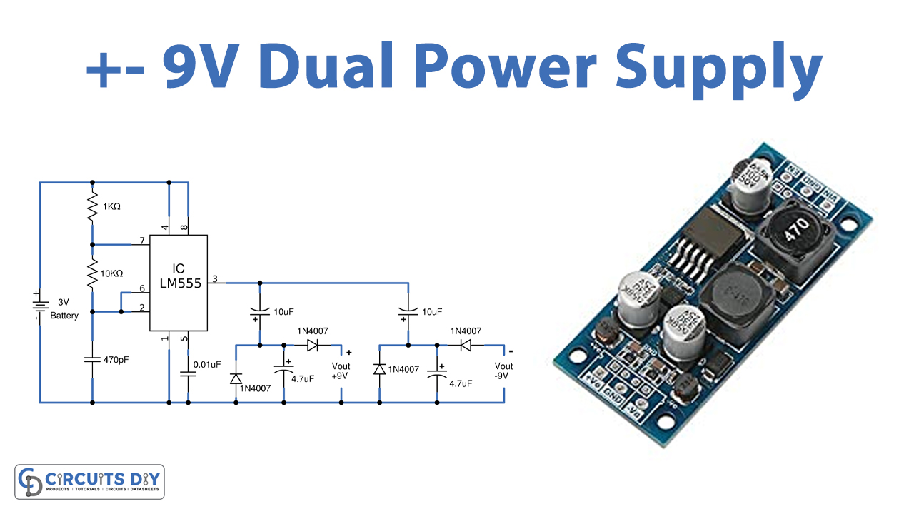
In this tutorial, we are going to make a “9V Dual Power Supply from 3V”.
Let’s say you need a dual power supply to operate multiple components in your project, it is surely inconvenient to use two power supply sources because it not only makes your simple project costly but also bulky. In this article simple +/-9V, Dual Power Supply from a 3V supply prototype is designed by using Timer IC 555 as the main element, you can boost and invert from a single power supply source. This IC is very useful, has low cost, and is easily available anywhere.
A 555 timer is a versatile IC that is used in oscillator, timer, and pulse generation applications. In this project Output square pulse from the timer, IC 555 is converted into positive and negative by using a rectifier diode setup. This circuit provides positive 9 volts and negative 9 volts as output by utilizing a 3V power source.

Hardware Components
The following components are required to make 9V Dual Power Supply Circuit
| S.no | Component | Value | Qty |
|---|---|---|---|
| 1. | IC | NE555 timer | 1 |
| 2. | Diode | 1N4007 | 4 |
| 3. | Resistor | 1KΩ, 10KΩ | 1, 1 |
| 4. | Electrolyte Capacitor | 10µF, 4.7µF | 2, 2 |
| 5. | Ceramic capacitor | 470pF, 0.01µF | 1, 1 |
| 6. | Power Supply | 3V |
555 Timer Pinout

For a detailed description of pinout, dimension features, and specifications download the datasheet of 555 Timer
9V Dual Power Supply Circuit
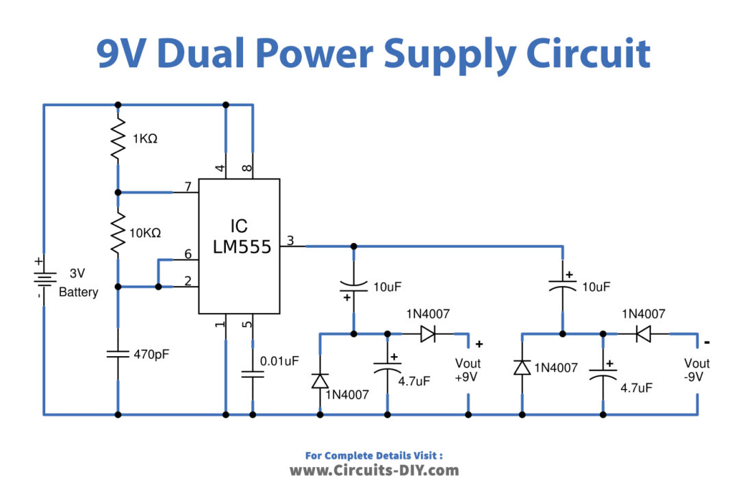
Working Explanation
Dual inline package 8-pin timer IC is used in this prototype circuit. The Timer IC 555 is a highly stable device for generating accurate time delays or oscillation. It can operate by using 3 volts to 12 volts. In this boost converter circuit, IC 555 is configured in Astable multivibrator mode that is pin 2 and 6 connected, it will trigger itself and free run as a multivibrator. The external capacitor C1 charges through R1 + R2 and discharges through R2 hence the duty cycle is set by the ratio of these two-timing resistors.
In the astable multivibrator mode of operation, the capacitor C1 charges and discharges between 1/3 Vcc and 2/3 Vcc. C3 and C5 Capacitors are used for charging and discharging the voltage by square pulse, hence it oscillates constant continuous square output pulse. The oscillating frequency depends on the timing Resistor and timing Capacitors.
Th = 0.693 * (R1 + R2) * C1
Tl = 0.693 * R2 * C1
Period = 0.693 * (R1 + 2*R2) * C1
Frequency = 1.44/(R1 + 2*R2) * C1
There are two types of rectification setup is made diodes and capacitors for positive and negative conversion. Now the output pulse from the timer IC is directly applied to the rectification setup. As we know square pulse has Positive and Negative sides and by rectification, we can remove unwanted parts. Here first rectification circuit removes the negative part and provides +9V, the second rectification circuit removes the positive part and provides -9V output.
Applications
It can be used in operational amplifiers.
It can be used in DC motors.