In this tutorial, we are making a Smart Universal Automatic Battery Charger. This charger will charge all your rechargeable batteries automatically when the battery voltage falls on the preset level. You can use this charger to charge batteries of different kinds and voltages. This circuit is using two ICs along with some other external components. It is an inexpensive circuit and a great project for electronic hobbyists.

Hardware Components
The following components are required to make Automatic Battery Charger Circuit
| S.no | Component | Value | Qty |
|---|---|---|---|
| 1. | IC | NE555 Timer | 1 |
| 2. | Op-amp IC | LM358 | 1 |
| 3. | LED | – | 4 |
| 4. | Relay | – | 1 |
| 5. | Diode | 1N4007 | 1 |
| 6. | Transistor | 2N3906 | 1 |
| 7. | Optocoupler | PC817 | 2 |
| 8. | Zener diode | 3V | 1 |
| 9. | Resistor | 10K, 1M, 470R | 1, 2, 6 |
| 10. | Variable Resistor | 10K | 2 |
NE555 IC Pinout

For a detailed description of pinout, dimension features, and specifications download the datasheet of 555 Timer
LM358 Pinout

For a detailed description of pinout, dimension features, and specifications download the datasheet of LM358
Automatic Battery Charger Circuit
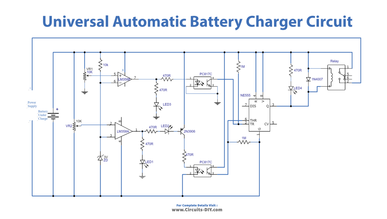
Working Explanation
We are using an operational amplifier IC LM358 that has two built-in op-amps. These two op-amps are working as a comparator to detect the voltage of the battery. Both are connected with variable resistors VR1 and VR2. They are used to set start and stop voltages for the charging process of the battery. When the battery’s charging is full LED1 will glow. The LED4 will indicate that the battery is getting charged.
You can connect the relay to the main plug of the power supply. In this way, it will switch ON the whole charger circuit from the mains when the battery needs to be charged and switches off when the battery is charged fully. This will save a lot of power.
Circuit Tuning
A simple tuning needs to be done to charge the battery automatically. For that, you will need an adjustable power supply and follow these steps. Since the voltage of a fully charged 6V battery s 7.3V on a DMM so set 7.3V on the adjustable power supply. Now replace the power supply in this circuit with the adjustable power supply and do not connect any battery with the circuit. Adjust the VR2 until LED1 glows.
Now to set the start voltage of charging change the voltage of the adjustable power supply to 5.9V. Adjust the VR2 until the LED3 turns off. The circuit is tuned now you can connect the power supply back and remove the adjustable power supply. The same procedure is done for other batteries. But the start and stop voltages will be set according to the battery’s voltage.