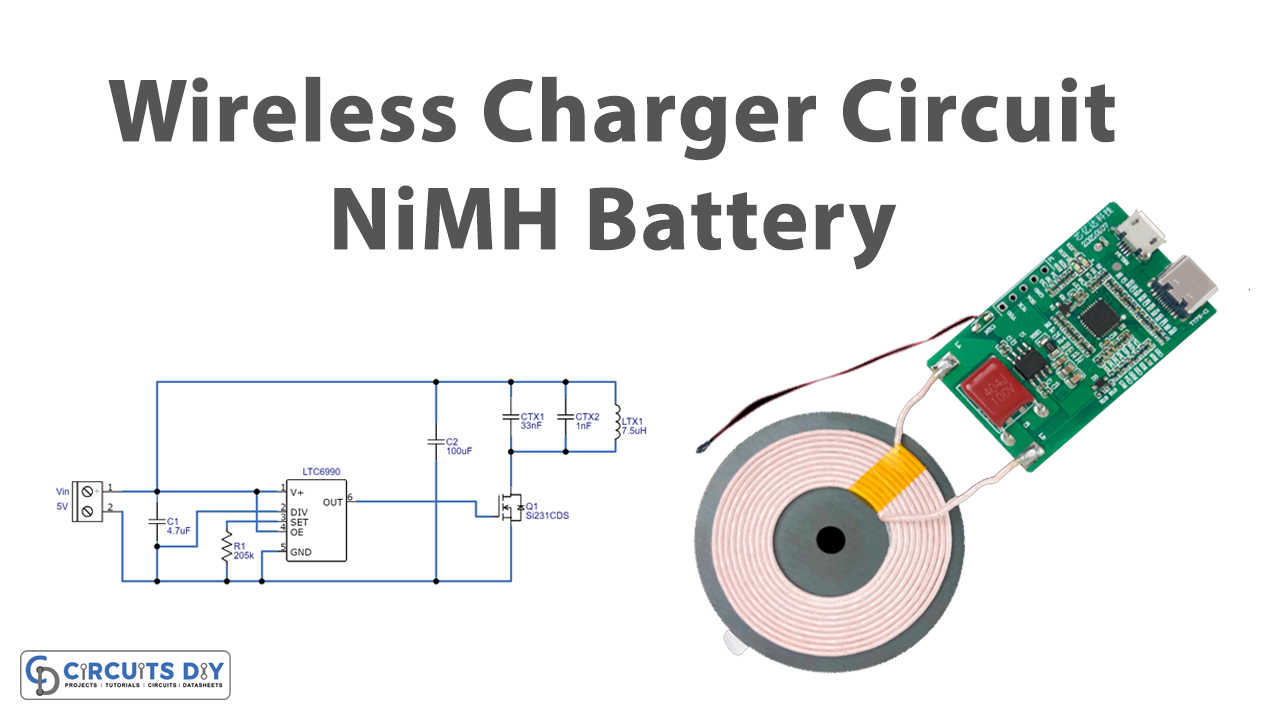
Introduction
As technology is evolving more and more, the devices now involve fewer wires or no wires. There was a time when people used telephones for communication, now there was a time when wireless communication is the easiest thing on this planet Earth, through mobile phones. In the same vein, in the past, most people used a PC that contained dozens of wires but now laptops have taken their place. It’s not critical to understand that as humans we need portable devices that have fewer wires. And, we all know that all electronic devices need a charger to charge their batteries. Commonly, chargers are not wireless. But the fact is that the wireless chargers are now the real thing. So for this tutorial, we have decided to create a “Wireless Charger Circuit NiMH Battery”
Hardware Components
The following components are required to make Wireless Charger Circuit
| S.no | Component | Value | Qty |
|---|---|---|---|
| 1. | IC | LTC6990 | 1 |
| 2. | Transistor | Si2312CDS | 1 |
| 3. | Diode | 1N5821 | 1 |
| 4. | Inductor | 7LTX17.5µH | 1 |
| 5. | SMD Capacitor | 4.7µF, 100µF, 33nF, 1nF | 1 |
| 6. | 2-Pin Connector | – | 2 |
LTC6990 Pinout

For a detailed description of pinout, dimension features, and specifications download the datasheet of LTC6990
Wireless Charger Circuit
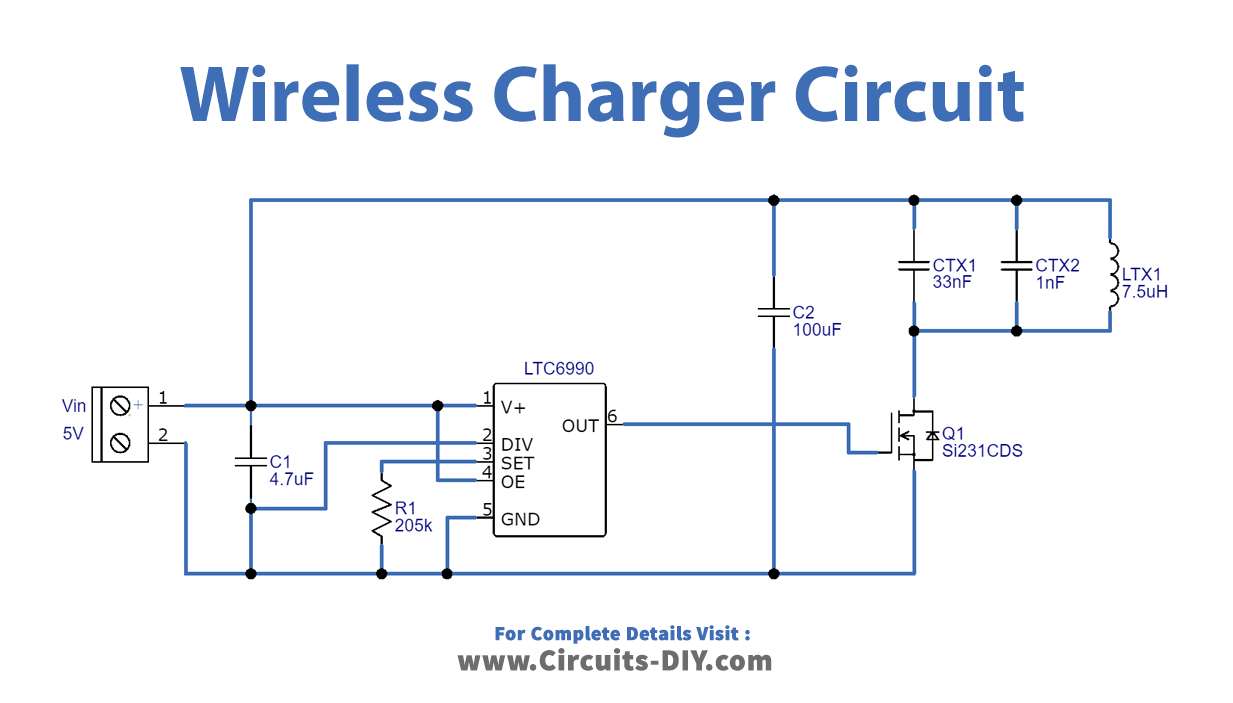
Working Explanation
This Wireless Charger Circuit is easy to make and understand. It uses the LTC6990HDCBTRPBF IC. Pin 1 is for the supply voltage which must be kept free from the noise. We have given the 5V supply to this pin. Pin 3is for the frequency setting. Pin 4 is the output enable pin which enables the output driver. And, Pin 6 provides the output. Transistor Si2312CDS is wired at the output pin, which works as the load switch for portable applications. The capacitors and the wireless charging coil Inductor 7LTX17.5µH are connected to pin one of this N channel MOSFET, which enables to charging of the devices wirelessly.
Application and Uses
To wirelessly charge various electronic devices.