This is a tutorial on one of the most useful DIY projects, a battery backup for multiple equipments. Battery backups are an essential part of various situations such as when equipment needs to be working without and disconnection due to power outages. Or it can be also used as a power bank for many equipments.
This circuit can be adjusted for multiple power outputs ranging from 1.2V to 12V with up to 1.5A current. It is fully automatic and does not need any maintenance for several months to a year after its properly built and adjusted. It also automatically disconnects the battery from the equipment when it is low. This saves the battery from deep discharge and extends its life.
Hardware Components
The following components are required to make Battery Backup Circuit
| S.no | Component | Value | Qty |
|---|---|---|---|
| 1. | SLA battery | 12V/10AH | 1 |
| 2. | Diode | 1N5408, 1N4148 | 1, 3 |
| 3. | Transistor | BC548, 2N4401, 2N4403, TIP32 | 1, 1, 2, 1 |
| 4. | Regulator IC | LM317T | 1 |
| 5. | Heatsinks | – | 1 |
| 6. | Zener diode | 6.2V | 1 |
| 7. | Relay | – | 1 |
| 8. | LED | – | 1 |
| 9. | Switch | – | 1 |
| 10. | Resistor | 1K, 10K, 5K, 120Ω, 470Ω, 240Ω, 470R, 4.7K, 0.5Ω | 5, 1, 1, 1, 1, 1, 1, 1, 1 |
| 11. | Potentiometer | 1KΩ | 1 |
| 12. | Ceramic Capacitor | 100nF, 0.22uF | 1, 1 |
| 13. | Electrolytic Capacitor | 10µF/50V | 1 |
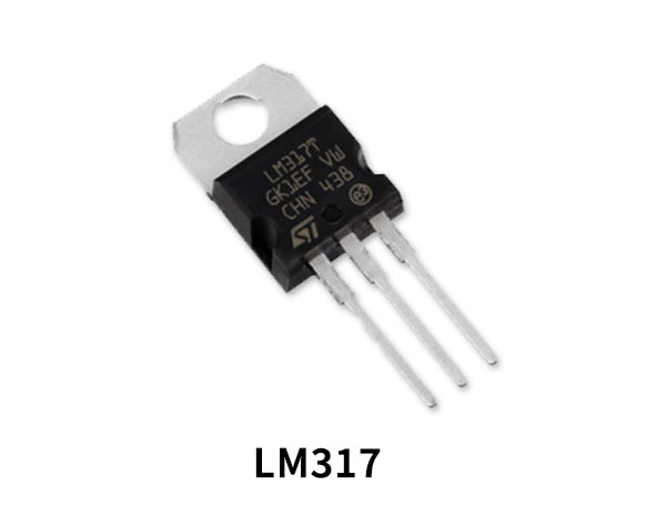
LM317 Pinout

For a detailed description of pinout, dimension features, and specifications download the datasheet of LM317T
2N4403 Pinout
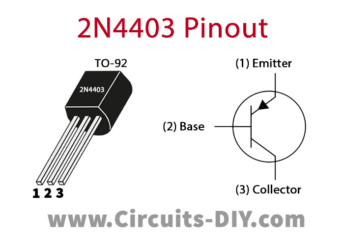
For a detailed description of pinout, dimension features, and specifications download the datasheet of 2N4403
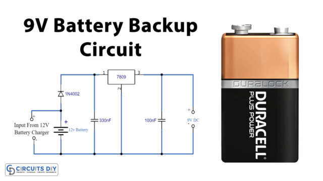
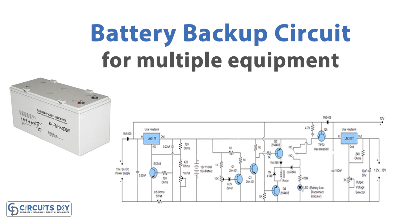
Battery Backup Circuit
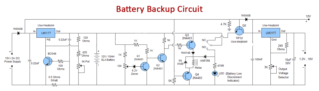
Working Explanation
The first section of this circuit is an automatic battery charger circuit. It will charge the 12V/10AH battery connected to this circuit and disconnect it from the supply when it is fully charged. In the second part, there is a battery backup circuit. A voltage regulator IC LM317T is used to provide a regulated voltage at the output which can be adjusted from 1.2V to 12V. We have used an LED in this circuit for the indication of a low battery state.
In order to select the desired output voltage, we have used a 3K potentiometer at the output of this circuit. You can use lower AH SLA batteries if you want instead of 12V/10AH as shown in the circuit diagram.
Circuit Adjustments
After completion of the circuit following adjustments are required initially,
- Disconnect all power sources like 15V supply and the battery.
- Take a variable power supply, set the voltage to 11V, and connect it to the place of the battery in the circuit.
- Adjust 10K variable resistor connected with 6.2V Zener diode until the LED turns ON.
- Now the circuit is ready to be used. Remove the variable power supply and connect the 15V power supply and the SLA battery.