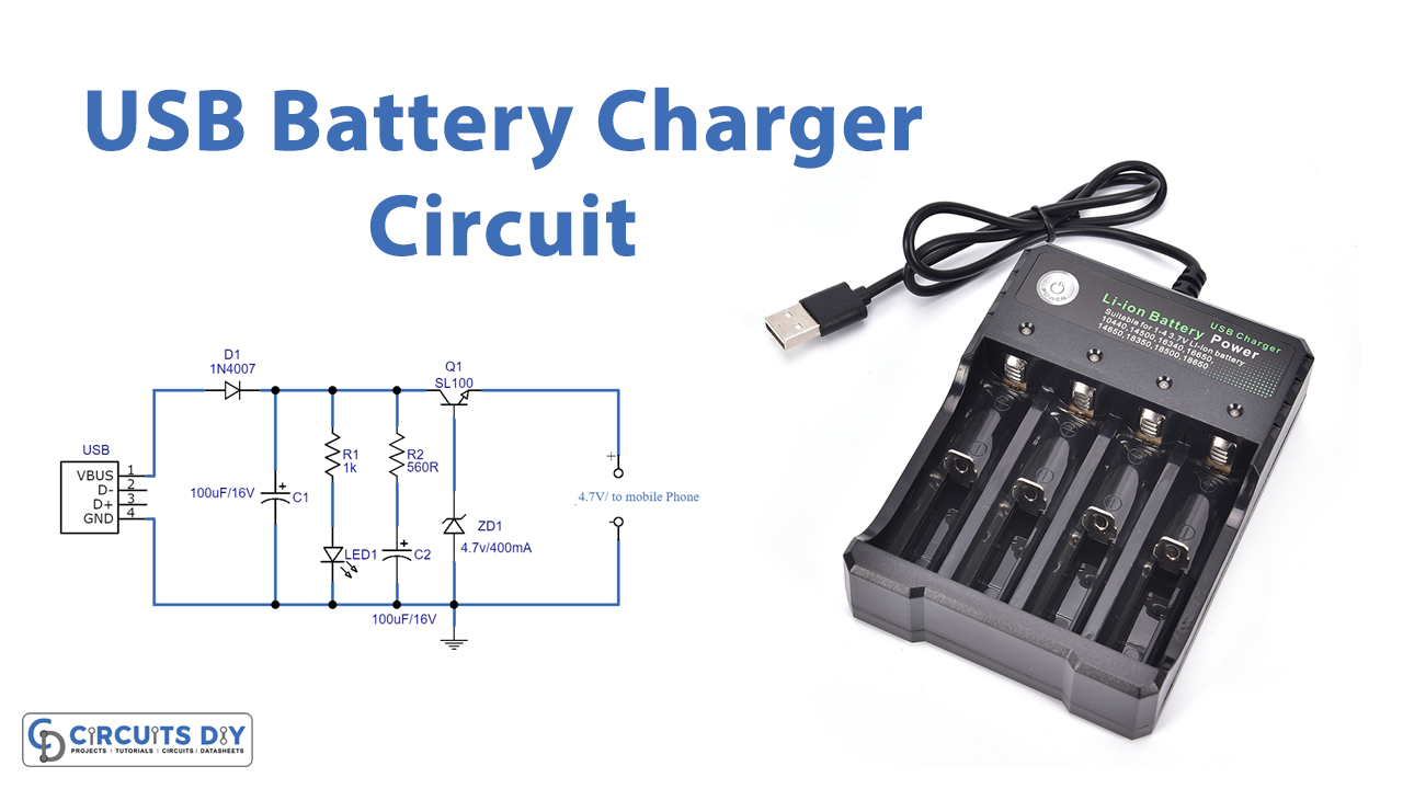
As each of our devices needs to be charged separately with its own charger. When you are on your way away from home, you must always keep an eye on your charging device. Because you might not be able to charge your gadget without its own charger. Thankfully, the invention of the Universal Serial Bus (USB) charger has resolved this issue. Recharging your devices is no longer a concern. With a USB charger, you can do it quickly and conveniently. It became popular because of its low cost of installation on any device and its compatibility with multiple platforms.
Hardware Required
| S.no | Component | Value | Qty |
|---|---|---|---|
| 1. | Zener Diode | 4.7V/400mW | 1 |
| 2. | Transistor | SL100 | 1 |
| 3. | Diode | 1N4007 | 1 |
| 4. | Resistor | 1KΩ,560Ω | 1,1 |
| 5. | Capacitor | 100uF/16V | 2 |
| 6. | LED | – | 1 |
Circuit Diagram
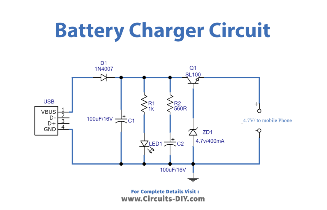
Working Explanation
As we can see, this USB power mobile charger circuit is constructed by using a Zener diode (4.7V/400mW) and switching transistor SL100. Here the USB port gives DC bias from pin1 and pin4, then the power supply is regulated through the Zener diode depending on the regulating voltage range. Choose the Zener diode as per the mobile battery specifications and requirements, at the end output pin gives a regulated power supply. . Before trying this circuit take extra care of mobile battery specifications.
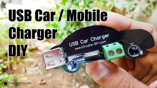
Applications
It can be used to charge an electrical device using a USB port, such as laptops, computer mice, smartphones, printers, keyboards, etc.
The circuit as illustrated will not function. There is no current supplied to the base of Q1.
Supplying current from R2/C1, components not otherwise serving a purpose, will turn Q1 on. But then there is no current limit as needed for a battery charger. Is this circuit intended to supply a device with a built in battery charge controller?
Next, the output in the corrected circuit would not be 4.7V, but closer to 4V because of the drop in Q1.
Last, with a nominal 5V input, only about 4.4V will be seen downstream of D1. Add the diode drop from Q1 and output is limited to ~3.8V.