A frequency-to-voltage converter is an electrical system that transforms the frequency of sinusoidal input into an equivalent current or output voltage. Frequency-to-voltage conversion transforms frequencies or signals such as voltage or current to the corresponding electrical output. It is an essential method for electromechanical calculations, where there are repetitive occurrences. When we have a frequency-to-voltage converter circuit over a range, a proportional DC output would be given.
Hardware Components
The following components are required to make the Frequency to Voltage Converter Circuit
| S.no | Component | Value | Qty |
|---|---|---|---|
| 1. | IC | KA331 | 1 |
| 2. | Resistors | 100K, 68K, 6.8K, 10K | 2,1,1,1 |
| 3. | Breadboard | – | 1 |
| 4. | Power supply | 15V | 1 |
| 5. | Ceramic Capacitors | 0.01uF, 470pF | 1, 1 |
| 6. | Electrolytic Capacitor | 1uF | 1 |
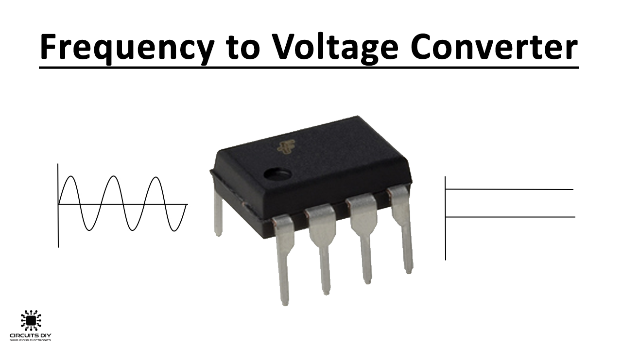
KA331 IC Pinout
For a detailed description of pinout, dimension features, and specifications download the datasheet of KA331
Frequency to Voltage Converter Circuit
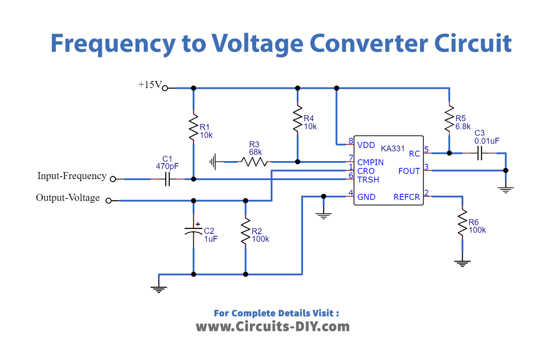
Working Explanation
The circuit input is linked to a 470pF C1 capacitor, which is linked further to the KA331 threshold pin (pin 6). Resistors R3 and R4 form the Voltage Divider Circuit that is attached to the KA331 Comparator pin 7. Capacitor C3 and Resistor R5 is the RC timer that provides the required oscillation over pin 5. Resistor R2 supplies the current of reference through pin 2. The circuit comes with a 15v voltage wired from pin 8 of the KA331.
This Frequency to Voltage Converter Circuit can be built on a PCB for greater precision. The key part of the circuit is the oscillator to RC. The RC oscillator has to be located in close proximity to the KA331 IC.
Application and Uses
- Hz to voltage converter is used in calculations and instrumentation.
- Speedometers often use this method in various kinds of sensor meters.