In this tutorial, we are going to make a “Simple Speech Amplifier Circuit”.
A voice amplifier is a small speaker that links to a microphone or microphone headset to make your voice louder. As to be heard in a crowd people have used megaphones for years, but modern technology has given us a much more decent solution.
If we want to develop an efficient audio amplifier, we should consider the input audio source and target output device or target loudspeaker specification. Because some designs are for noisy environments, while some are more ideal for simple tasks like talking.
Here we designed a Simple Speech Amplifier Circuit by using IC TDA7052A with consideration of condenser mic audio input and 8Ω loudspeaker output. The TDA7052A is a mono BTL output amplifier with DC Volume control. It has a mute mode, thermal protection, and short circuit protection, providing good overall stability for all ranges of signals.
Hardware Required
| S.no | Compnonet | Value | Qty |
|---|---|---|---|
| 1. | IC | TDA7052A | 1 |
| 2. | Variable Resistor | 100KΩ, 10KΩ, 330Ω, 1KΩ | 1,1,1,1 |
| 3. | Condenser Mic | – | 1 |
| 4. | Transistor | BC547 NPN | 1 |
| 5. | Variable Resistor POT | 20KΩ | 1 |
| 6 | Capacitors | 1µF, 10µF, 0.1µF | 1,1,1 |
| 7. | Loudspeaker | 8Ω | 1 |
| 8. | Connecting Wires | – | 1 |
| 9. | Power Supply | 9V | 1 |
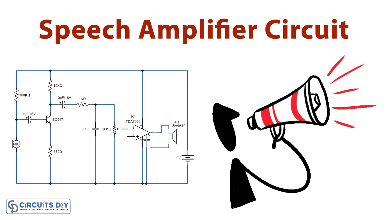
Circuit Diagram

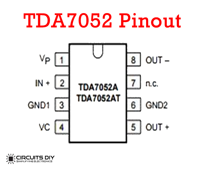
IC TDA7052A Pin Details
Working Explanation
The circuit design is based on the audio power amplifier IC TDA 7052. IC TDA7052A is used here as the main part, it is an 8-pin dual inline package IC, also comes in an SO8 plastic package. The IC can deliver a maximum power output of 1.2 W at a 6V supply when we use an 8Ω RL loudspeaker. Requires few external components to design full amplifier circuit. Here we use the Condenser mic as an audio input source hence it requires a pre-amplifier stage, Condenser mic receives bias through R1 Resistor and is connected to the transistor base through the C1 capacitor.
The audio signal from the mic is pre-amplified by the amplifier based on Q1 (BC 547). Transistor Q1 Increases the audio signal strength, then output from Q1 is connected to Positive input pin 2 of TDA7052A through coupling capacitor C2 and Variable Resistor RV1. Now, this RV1 acts as a volume control potentiometer. The capacitor C3 is used to bye-pass the upper frequencies in order to avoid Larsen’s effect (the microphone picking up speaker output to cause howls).9V DC supply is connected to Bias pins of TDA7052A. 8Ω Loudspeaker is connected with output pins 5 and 8.
Applications
Anyone who needs to give a speaking presentation in a sizable space could benefit from a voice amplifier, it is commonly used by teachers, lecturers, tour guides, and people at rallies and protests.