Water overflow is a common problem that everyone faces and it eventually leads to the wastage of water. There are a lot of solutions to this problem such as ball valves etc. But you can also solve this problem by using a little electronics. Here is a tutorial of a simple and handy DIY water level buzzer circuit. It detects the level of water and the buzzer produces sound when the water reaches the preset level or when the container gets full.
This circuit is simple and inexpensive as it using only a few parts like Transistor, buzzer, resistor, and a power supply/battery. We are using BC547B transistor but you can use any other general-purpose transistor like, 2N222 or 2N3904.
Hardware Components
| S.no | Component | Value | Qty |
|---|---|---|---|
| 1. | Input Supply DC | 9V | 1 |
| 2. | Buzzer | 9V | 1 |
| 3. | Probes | – | 2 |
| 4. | NPN Transistor | BC547B | 1 |
| 5. | Variable Resistor | 300KΩ | 1 |
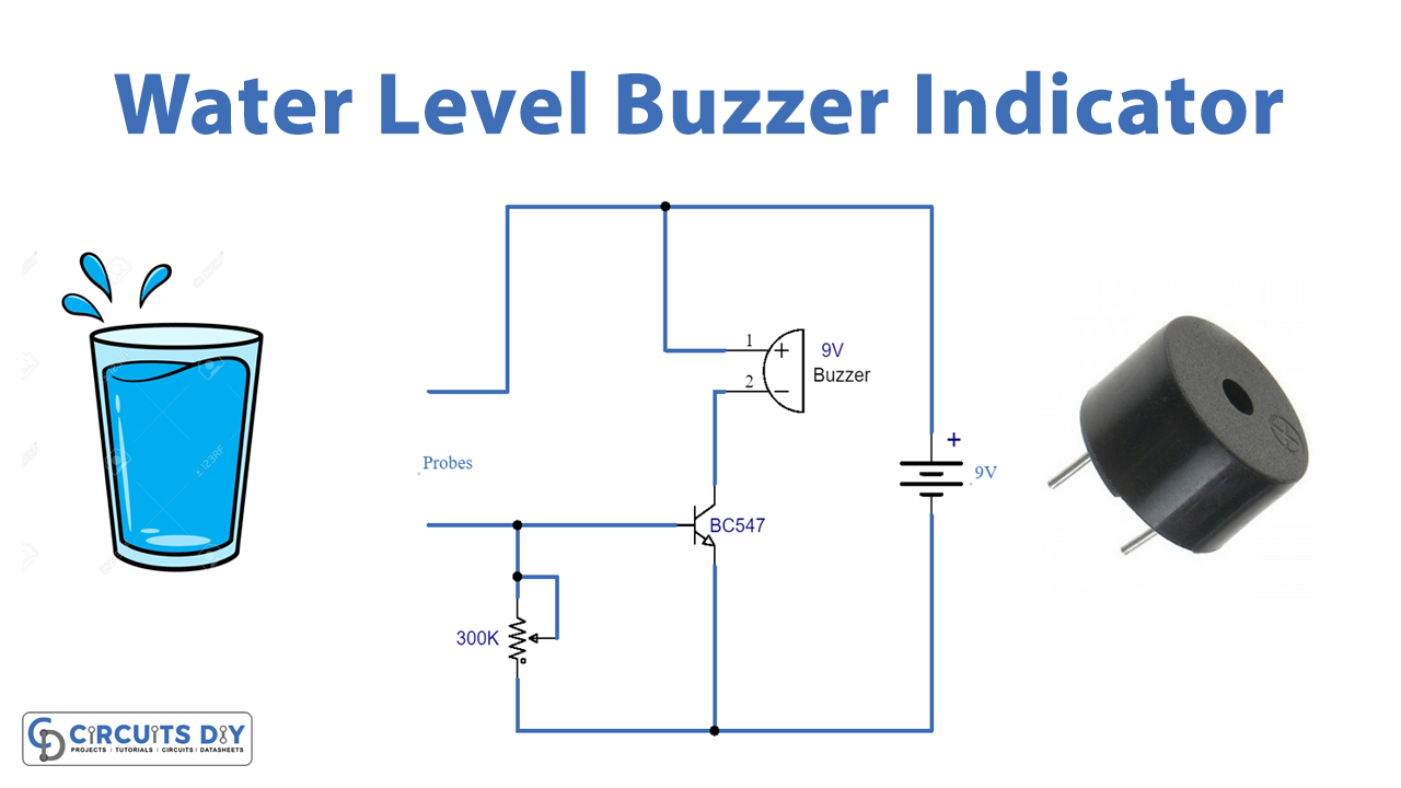
Circuit Diagram
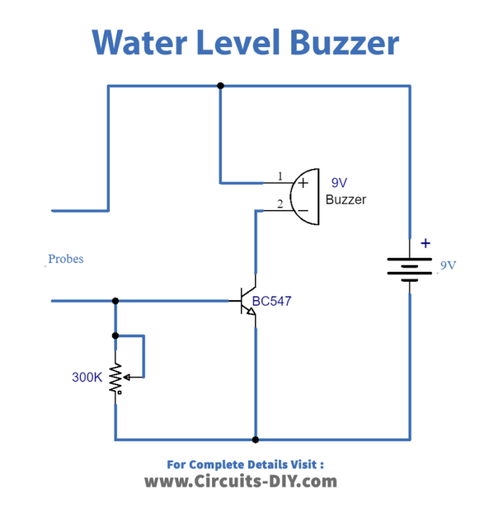
Working Explanation
This circuit can be operated at 9 volts. Here we are using an NPN transistor which acts as a Switch. Initially, no voltage is going to the base of the transistor and it is in OFF state and no current is flowing through the collector to emitter that’s why the buzzer is off too.
When the probes detect water the transistor gets the voltage because water is a conductor of electricity. When transistor starts conducting it lets the current flow from collector to emitter and as a result Buzzer is activated. A 300K variable resistor is used to adjust the level of the water to be detected at.
Applications and Uses
This circuit can be used to sense or detect the water in
- Tanks
- Washing Machines
- Swimming Pools or any other containers.