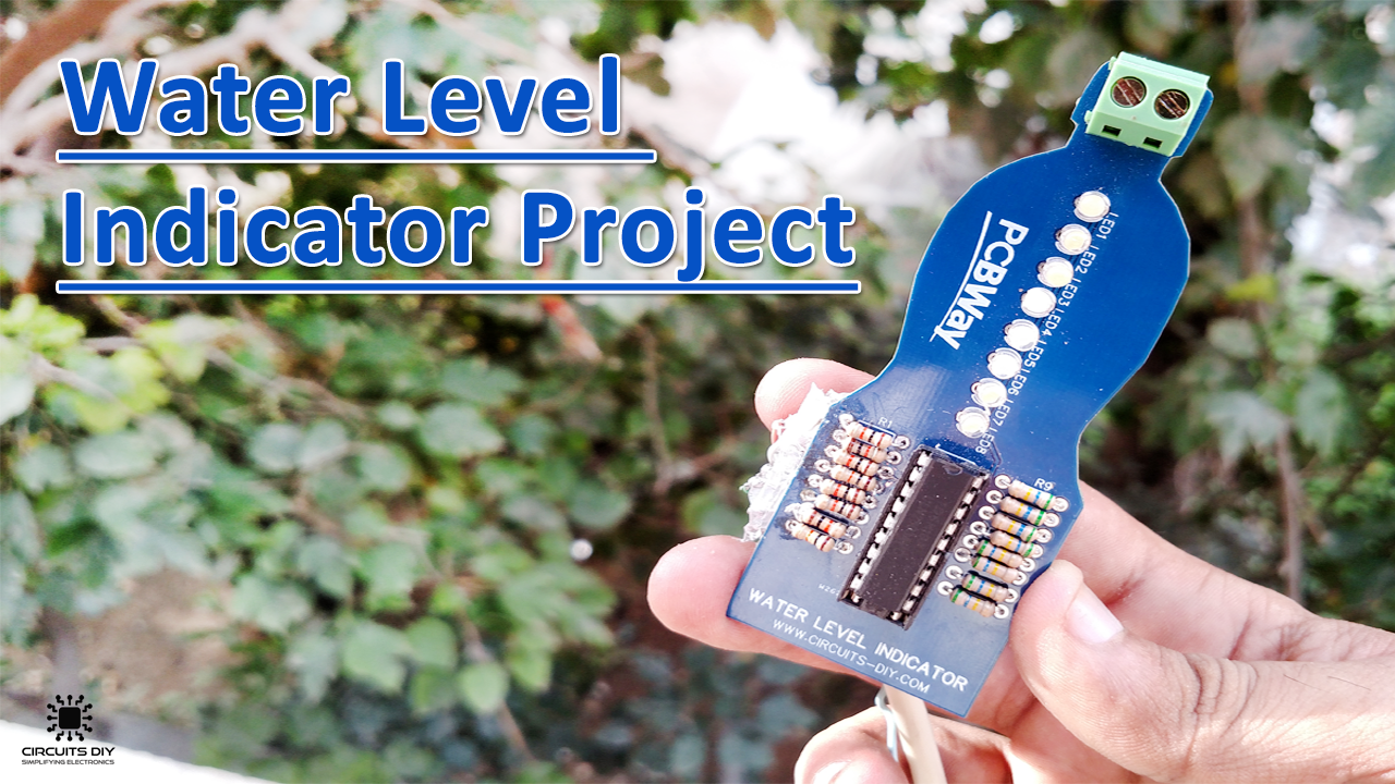
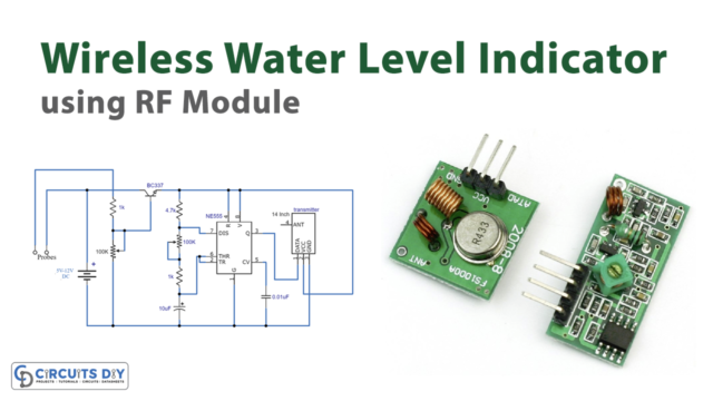
A Water level indicator is a simple electronic circuit that can indicate the level of any conductive, non-corrosive liquid contained in a vessel such as a reservoir, overhead/underhead tank, container, etc. So, in today’s tutorial, we will understand how to build a water level indicator circuit using a ULN2803 Darlington transistor Array IC.
ULN2803 is a High voltage, high current Transistor Array IC used especially with Microcontrollers where we need to drive high power loads. This IC consists of eight NPN Darlington-connected transistors with common Clamp diodes for switching the loads connected to the output. This IC widely serves in driving high loads such as Lamps, relays, motors, etc. It is usually rated at 50v/500mA.
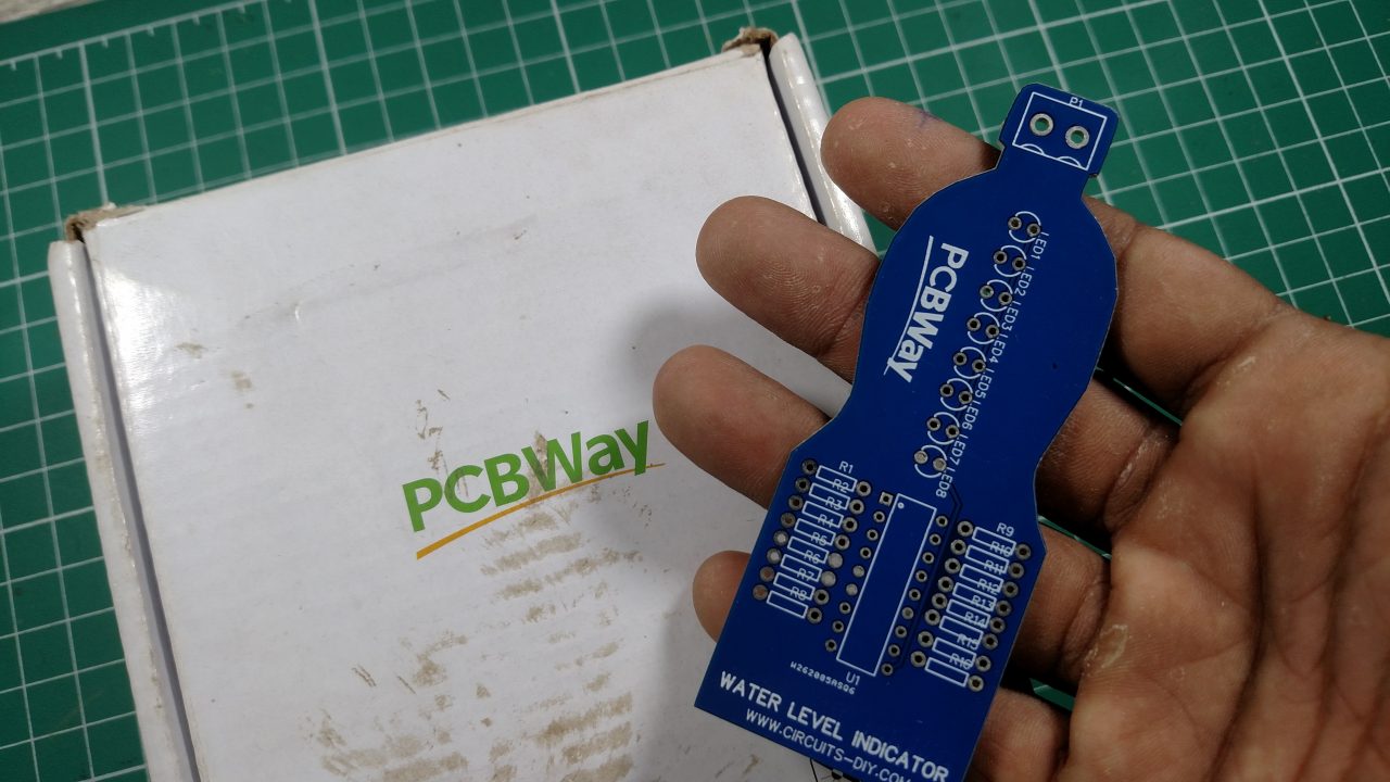
PCBWay commits to meeting the needs of its customers from different industries in terms of quality, delivery, cost-effectiveness, and any other demanding requests. As one of the most experienced PCB manufacturers in China. They pride themselves to be your best business partners as well as good friends in every aspect of your PCB needs.
Hardware Components
You will need the following parts to build this project
| S.no | Component | Value | Qty |
|---|---|---|---|
| 1. | Darlington transistor IC | ULN2803 | 1 |
| 2. | LED (RED) | 5mm | 8 |
| 3. | Resistor | 10KΩ, 560Ω | 1,1 |
| 4. | DC Power Supply | 12V | 1 |
| 5. | Battery Clips | – | 1 |
| 6. | Connecting Wire | – | 1 |
| Pin Name | Pin No. | Description |
| 1B – 8B | 1 – 8 | Base Terminal For Transistor Array |
| GND | 9 | Emitter connection for all Transistors |
| COM | 10 | Common Cathode (-ve) node for flyback diodes |
| 8C – 1C | 11 – 18 | Collector Terminal For Transistor Arrays |
Circuit Diagram

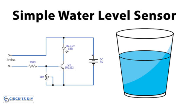
Working Explanation
The heart of this circuit is a ULN2803 IC. The Working of this circuit is pretty simple, the base terminal of all transistors are connected from PIN 1 to PIN 8 (1B – 8B), functioning as an individual probe for each level, while the positive rail is used as the bottom probe going through the container/reservoir. When the water level reaches each probe it will make electrical connectivity between the positive rail and the probe due to which the associated LED will light up. The operating voltage of the circuit is 12V DC.
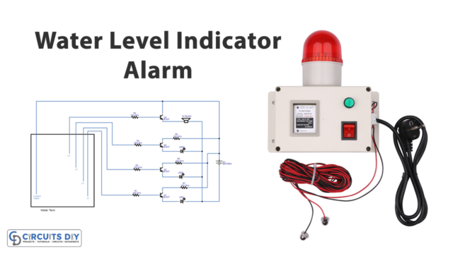
Applications
- Can be used in places such as Factories, Manufacturing complexes, apartments & homes
- An important part of wide-scale industrial processes such as cooling tower water level control, life station switches, tsunami warning systems, irrigation control, fuel tank level gauging & sump pumps

I want a battery charger cct with a F.E.T. out put (n-channel) and for 27 volts.