
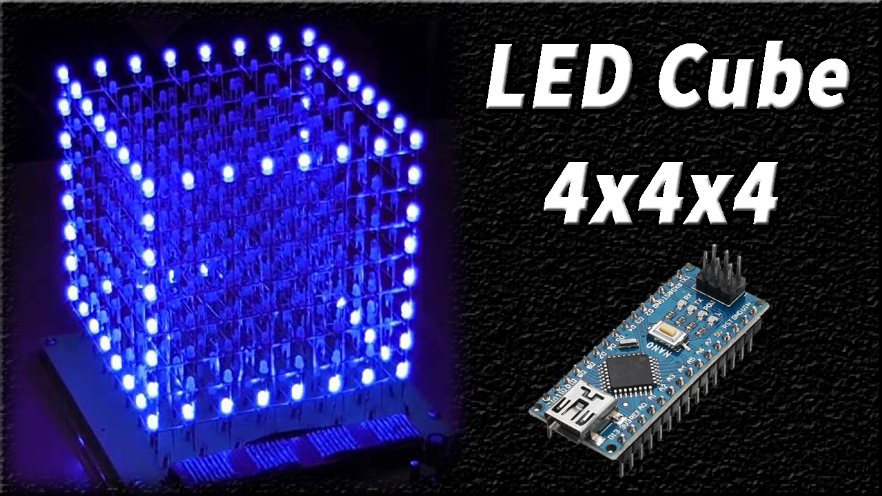
An LED Cube can be thought of as an LED screen, in which simple 5mm LED’s play the role of digital pixels. A LED cube allows us to create images and patterns by using the concept of an optical phenomenon known as persistence of vision (POV). So, In this tutorial, we will go over a step by step procedure on how to build a 4x4x4 LED cube using an Arduino nano. The cube has 64 blue LEDs that make up its 4 layers (positives) and 16 columns (negatives).
Arduino Nano is a compact, compatible, durable, and breadboard-friendly Microcontroller board based on the ATmega328p model. On a functional scale, it is pretty much similar to Arduino Duemilanove, but in a different package. It has no DC power jack like other models & requires a Mini-B USB cable to be powered by a laptop or PC.
JLCPCB is the foremost PCB prototype & manufacturing company in china, providing us with the best service we have ever experienced regarding (Quality, Price Service & Time).
Hardware Required
You will need the following parts for creating LED Cube Project.
| S.no | Component | Value | Qty |
|---|---|---|---|
| 1 | Arduino Nano | – | 1 |
| 2 | USB Cable | Micro-B | 1 |
| 3 | LED | Diffused, 5mm | 64 |
| 4 | DC Hand Drill | – | 1 |
| 5 | Silver Wires | – | 40 |
| 6 | Female Headers | – | As per need |
| 7 | Resistor | 100 Ohms | 4 |
| 8 | Cardboard | – | As per need |
| 9 | Soldering Iron | 45W – 60W | 1 |
| 10 | Soldering Flux | – | 1 |
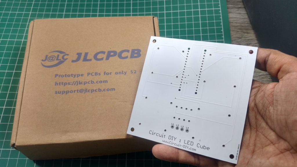
You can build a custom PCB Prototype in ($2) with JLCPCB’s Services.
Useful Steps
Follow all steps carefully from the video tutorial at the end of this post (Highly Recommended).
1) Take a 5×5 inch card piece and then make 9 square boxes with 1×1 inch spacing
2) Drill 5mm Hole to the corner of all boxes
3) Bend negative leg of LED with the help of a Screw Driver
4) Mark Arrow on Card Piece and then Insert all LED (negative leg ) facing the arrow.
5) Then solder all positive leg of the 16 LED with a silver wire & then test the LED using a multimeter.
6) After making 4-row using similar technique connect all negative leg of led using silver wires
7) Connect L1, L2, L3, & L4 To Common positive of Row1, Row2, Row3, & Row4 Respectively
8) Then Solder Header onto the PCB Board
9) Solder Resistors
10) Upload code and Power up circuit
Working Explanation
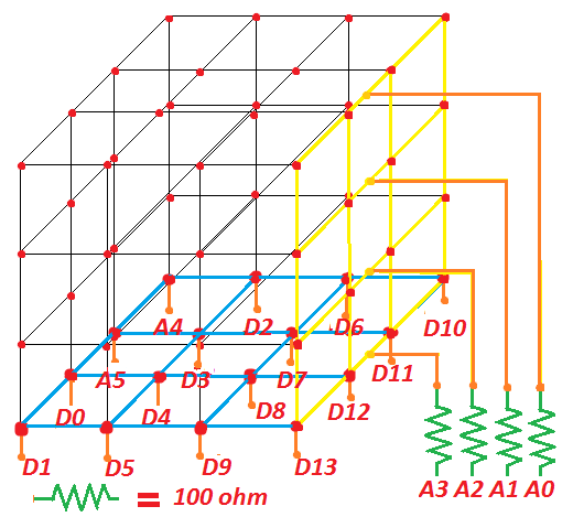
An LED cube inhabits the principle of persistence of vision. the working of this circuit is as follows. All the 4 layers of the LED cube are defined as A0, A1, A2 & A3 while all the 16 columns of the cube are defined as (0 – 13 & A4, A5). Upon uploading the code, the controller registers all the layers and columns of the cube corresponding to the adjoining pins & sets the time integer to 250.
The controller then defines 2 loops associated with the output of the layers & columns. Here, we have SET the function randomseed() to intake analog input from pin 10 for random loop function selection. After this the controller enters the void loop() routine & randomly goes through each LED display function.
Applications
- Usually used for decorative purposes in places such as wedding & community halls.
- Can also be used to teach the phenomenon of persistence of vision (POV).
Code
/*
  4x4x4 LED Cube
  Connection Setup:
  Columns
  [(x,y)-Pin]
  (1,1)-13
  (1,2)-12
  (1,3)-11
  (1,4)-10
  (2,1)-9
  (2,2)-8
  (2,3)-7
  (2,4)-6
  (3,1)-5
  (3-2)-4
  (3-3)-3
  (3,4)-2
  (4,1)-1
  (4,2)-0
  (4,3)-A5
  (4,4)-A4
  Layers
  [layer-Pin]
  a-A0
  b-A1
  c-A2
  d-A3
*/
//initializing and declaring led rows
  int column[16]={13,12,11,10,9,8,7,6,5,4,3,2,1,0,A5,A4};
//initializing and declaring led layers
  int layer[4]={A3,A2,A1,A0};
  int time = 250;

void setup()
{
  //setting rows to ouput
  for(int i = 0; i<16; i++)
  {
    pinMode(column[i], OUTPUT);
  }
  //setting layers to output
  for(int i = 0; i<4; i++)
  {
    pinMode(layer[i], OUTPUT);
  }
  //seeding random for random pattern
  randomSeed(analogRead(10));
}
void loop()
{
  turnEverythingOff();//turn all off
  flickerOn();
  turnEverythingOn();//turn all on
  delay(time);
  turnOnAndOffAllByLayerUpAndDownNotTimed();
  layerstompUpAndDown();
  turnOnAndOffAllByColumnSideways();
  delay(time);
  aroundEdgeDown();
  turnEverythingOff();
  randomflicker();
  randomRain();
  diagonalRectangle();
  goThroughAllLedsOneAtATime();
  propeller();
  spiralInAndOut();
  flickerOff();
  turnEverythingOff();
  delay(2000);
}
//turn all off
void turnEverythingOff()
 {
   for(int i = 0; i<16; i++)
   {
     digitalWrite(column[i], 1);
   }
   for(int i = 0; i<4; i++)
   {
     digitalWrite(layer[i], 0);
   }
 }

////////////////////////////////////////////////////////////turn all on
void turnEverythingOn()
{
  for(int i = 0; i<16; i++)
  {
    digitalWrite(column[i], 0);
  }
  //turning on layers
  for(int i = 0; i<4; i++)
  {
    digitalWrite(layer[i], 1);
  }
}
///////////////////////////////////////////////////////turn columns off
void turnColumnsOff()
{
  for(int i = 0; i<16; i++)
  {
    digitalWrite(column[i], 1);
  }
}
/////////////////////////////////////////////////////////////flicker on
void flickerOn()
{
  int i = 150;
  while(i != 0)
  {
    turnEverythingOn();
    delay(i);
    turnEverythingOff();
    delay(i);
    i-= 5;
  }
}
//////////////turn everything on and off by layer up and down NOT TIMED
void turnOnAndOffAllByLayerUpAndDownNotTimed()
{
  int x = 75;
  for(int i = 5; i != 0; i--)
  {
    turnEverythingOn();
    for(int i = 4; i!=0; i--)
    {
      digitalWrite(layer[i-1], 0);
      delay(x);
    }
    for(int i = 0; i<4; i++)
    {
      digitalWrite(layer[i], 1);
      delay(x);
    }
      for(int i = 0; i<4; i++)
    {
      digitalWrite(layer[i], 0);
      delay(x);
    }
    for(int i = 4; i!=0; i--)
    {
      digitalWrite(layer[i-1], 1);
      delay(x);
    }
  }
}
//////////////////////////turn everything on and off by column sideways
void turnOnAndOffAllByColumnSideways()
{
  int x = 75;
  turnEverythingOff();
  //turn on layers
  for(int i = 0; i<4; i++)
  {
    digitalWrite(layer[i], 1);
  }
  for(int y = 0; y<3; y++)
  {
    //turn on 0-3
    for(int i = 0; i<4; i++)
    {
      digitalWrite(column[i], 0);
      delay(x);
    }
    //turn on 4-7
    for(int i = 4; i<8; i++)
    {
      digitalWrite(column[i], 0);
      delay(x);
    }
    //turn on 8-11
    for(int i = 8; i<12; i++)
    {
      digitalWrite(column[i], 0);
      delay(x);
    }
    //turn on 12-15
    for(int i = 12; i<16; i++)
    {
      digitalWrite(column[i], 0);
      delay(x);
    }
    //turn off 0-3
    for(int i = 0; i<4; i++)
    {
      digitalWrite(column[i], 1);
      delay(x);
    }
    //turn off 4-7
    for(int i = 4; i<8; i++)
    {
      digitalWrite(column[i], 1);
      delay(x);
    }
    //turn off 8-11
    for(int i = 8; i<12; i++)
    {
      digitalWrite(column[i], 1);
      delay(x);
    }
    //turn off 12-15
    for(int i = 12; i<16; i++)
    {
      digitalWrite(column[i], 1);
      delay(x);
    }
    //turn on 12-15
    for(int i = 12; i<16; i++)
    {
      digitalWrite(column[i], 0);
      delay(x);
    }
    //turn on 8-11
    for(int i = 8; i<12; i++)
    {
      digitalWrite(column[i], 0);
      delay(x);
    }
    //turn on 4-7
    for(int i = 4; i<8; i++)
    {
      digitalWrite(column[i], 0);
      delay(x);
    }
    //turn on 0-3
    for(int i = 0; i<4; i++)
    {
      digitalWrite(column[i], 0);
      delay(x);
    }
    //turn off 12-15
    for(int i = 12; i<16; i++)
    {
      digitalWrite(column[i], 1);
      delay(x);
    }
    //turn off 8-11
    for(int i = 8; i<12; i++)
    {
      digitalWrite(column[i], 1);
      delay(x);
    }
    //turn off 4-7
    for(int i = 4; i<8; i++)
    {
      digitalWrite(column[i], 1);
      delay(x);
    }
    //turn off 0-3
    for(int i = 0; i<4; i++)
    {
      digitalWrite(column[i], 1);
      delay(x);
    }
  }
}
/////////////////////////////////////////up and down single layer stomp
void layerstompUpAndDown()
{
  int x = 75;
  for(int i = 0; i<4; i++)
  {
    digitalWrite(layer[i], 0);
  }
  for(int y = 0; y<5; y++)
  {
    for(int count = 0; count<1; count++)
    {
      for(int i = 0; i<4; i++)
      {
        digitalWrite(layer[i], 1);
        delay(x);
        digitalWrite(layer[i], 0);
      }
      for(int i = 4; i !=0; i--)
      {
        digitalWrite(layer[i-1], 1);
        delay(x);
        digitalWrite(layer[i-1], 0);
      }
    }
    for(int i = 0; i<4; i++)
    {
      digitalWrite(layer[i], 1);
      delay(x);
    }
    for(int i = 4; i!=0; i--)
    {
      digitalWrite(layer[i-1], 0);
      delay(x);
    }
  }
}
////////////////////////////////////////////////////////////flicker off
void flickerOff()
{
  turnEverythingOn();
  for(int i = 0; i!= 150; i+=5)
  {
    turnEverythingOff();
    delay(i+50);
    turnEverythingOn();
    delay(i);
  }
}
///////////////////////////////////////////around edge of the cube down
void aroundEdgeDown()
{
  for(int x = 200; x != 0; x -=50)
  {
    turnEverythingOff();
    for(int i = 4; i != 0; i--)
    {
      digitalWrite(layer[i-1], 1);
      digitalWrite(column[5], 0);
      digitalWrite(column[6], 0);
      digitalWrite(column[9], 0);
      digitalWrite(column[10], 0);

      digitalWrite(column[0], 0);
      delay(x);
      digitalWrite(column[0], 1);
      digitalWrite(column[4], 0);
      delay(x);
      digitalWrite(column[4], 1);
      digitalWrite(column[8], 0);
      delay(x);
      digitalWrite(column[8], 1);
      digitalWrite(column[12], 0);
      delay(x);
      digitalWrite(column[12], 1);
      digitalWrite(column[13], 0);
      delay(x);
      digitalWrite(column[13], 1);
      digitalWrite(column[15], 0);
      delay(x);
      digitalWrite(column[15], 1);
      digitalWrite(column[14], 0);
      delay(x);
      digitalWrite(column[14], 1);
      digitalWrite(column[11], 0);
      delay(x);
      digitalWrite(column[11], 1);
      digitalWrite(column[7], 0);
      delay(x);
      digitalWrite(column[7], 1);
      digitalWrite(column[3], 0);
      delay(x);
      digitalWrite(column[3], 1);
      digitalWrite(column[2], 0);
      delay(x);
      digitalWrite(column[2], 1);
      digitalWrite(column[1], 0);
      delay(x);
      digitalWrite(column[1], 1);
    }
  }
}
/////////////////////////////////////////////////////////random flicker
void randomflicker()
{
  turnEverythingOff();
  int x = 10;
  for(int i = 0; i !=750; i+=2)
  {
  int randomLayer = random(0,4);
  int randomColumn = random(0,16);

  digitalWrite(layer[randomLayer], 1);
  digitalWrite(column[randomColumn], 0);
  delay(x);
  digitalWrite(layer[randomLayer], 0);
  digitalWrite(column[randomColumn], 1);
  delay(x);
  }
}
////////////////////////////////////////////////////////////random rain
void randomRain()
{
  turnEverythingOff();
  int x = 100;
  for(int i = 0; i!=60; i+=2)
  {
    int randomColumn = random(0,16);
    digitalWrite(column[randomColumn], 0);
    digitalWrite(layer[0], 1);
    delay(x+50);
    digitalWrite(layer[0], 0);
    digitalWrite(layer[1], 1);
    delay(x);
    digitalWrite(layer[1], 0);
    digitalWrite(layer[2], 1);
    delay(x);
    digitalWrite(layer[2], 0);
    digitalWrite(layer[3], 1);
    delay(x+50);
    digitalWrite(layer[3], 0);
    digitalWrite(column[randomColumn], 1);
  }
}
/////////////////////////////////////////////////////diagonal rectangle
void diagonalRectangle()
{
  int x = 350;
  turnEverythingOff();
  for(int count = 0; count<5; count++)
  {
    //top left
    for(int i = 0; i<8; i++)
    {
      digitalWrite(column[i], 0);
    }
    digitalWrite(layer[3], 1);
    digitalWrite(layer[2], 1);
    delay(x);
    turnEverythingOff();
    //middle middle
    for(int i = 4; i<12; i++)
    {
      digitalWrite(column[i], 0);
    }
    digitalWrite(layer[1], 1);
    digitalWrite(layer[2], 1);
    delay(x);
    turnEverythingOff();
    //bottom right
    for(int i = 8; i<16; i++)
    {
      digitalWrite(column[i], 0);
    }
    digitalWrite(layer[0], 1);
    digitalWrite(layer[1], 1);
    delay(x);
    turnEverythingOff();
    //bottom middle
    for(int i = 4; i<12; i++)
    {
      digitalWrite(column[i], 0);
    }
    digitalWrite(layer[0], 1);
    digitalWrite(layer[1], 1);
    delay(x);
    turnEverythingOff();
    //bottom left
    for(int i = 0; i<8; i++)
    {
      digitalWrite(column[i], 0);
    }
    digitalWrite(layer[0], 1);
    digitalWrite(layer[1], 1);
    delay(x);
    turnEverythingOff();
    //middle middle
    for(int i = 4; i<12; i++)
    {
      digitalWrite(column[i], 0);
    }
    digitalWrite(layer[1], 1);
    digitalWrite(layer[2], 1);
    delay(x);
    turnEverythingOff();
    //top right
    for(int i = 8; i<16; i++)
    {
      digitalWrite(column[i], 0);
    }
    digitalWrite(layer[2], 1);
    digitalWrite(layer[3], 1);
    delay(x);
    turnEverythingOff();
    //top middle
    for(int i = 4; i<12; i++)
    {
      digitalWrite(column[i], 0);
    }
    digitalWrite(layer[2], 1);
    digitalWrite(layer[3], 1);
    delay(x);
    turnEverythingOff();
  }
  //top left
  for(int i = 0; i<8; i++)
  {
    digitalWrite(column[i], 0);
  }
  digitalWrite(layer[3], 1);
  digitalWrite(layer[2], 1);
  delay(x);
  turnEverythingOff();
}
//////////////////////////////////////////////////////////////propeller
void propeller()
{
  turnEverythingOff();
  int x = 90;
  for(int y = 4; y>0; y--)
  {
    for(int i = 0; i<6; i++)
    {
      //turn on layer
      digitalWrite(layer[y-1], 1);
      //a1
      turnColumnsOff();
      digitalWrite(column[0], 0);
      digitalWrite(column[5], 0);
      digitalWrite(column[10], 0);
      digitalWrite(column[15], 0);
      delay(x);
      //b1
      turnColumnsOff();
      digitalWrite(column[4], 0);
      digitalWrite(column[5], 0);
      digitalWrite(column[10], 0);
      digitalWrite(column[11], 0);
      delay(x);
      //c1
      turnColumnsOff();
      digitalWrite(column[6], 0);
      digitalWrite(column[7], 0);
      digitalWrite(column[8], 0);
      digitalWrite(column[9], 0);
      delay(x);
      //d1
      turnColumnsOff();
      digitalWrite(column[3], 0);
      digitalWrite(column[6], 0);
      digitalWrite(column[9], 0);
      digitalWrite(column[12], 0);
      delay(x);
      //d2
      turnColumnsOff();
      digitalWrite(column[2], 0);
      digitalWrite(column[6], 0);
      digitalWrite(column[9], 0);
      digitalWrite(column[13], 0);
      delay(x);
      //d3
      turnColumnsOff();
      digitalWrite(column[1], 0);
      digitalWrite(column[5], 0);
      digitalWrite(column[10], 0);
      digitalWrite(column[14], 0);
      delay(x);
    }
  }
  //d4
  turnColumnsOff();
  digitalWrite(column[0], 0);
  digitalWrite(column[5], 0);
  digitalWrite(column[10], 0);
  digitalWrite(column[15], 0);
  delay(x);
}
//////////////////////////////////////////////////////spiral in and out
void spiralInAndOut()
{
  turnEverythingOn();
  int x = 60;
  for(int i = 0; i<6; i++)
  {
    //spiral in clockwise
    digitalWrite(column[0], 1);
    delay(x);
    digitalWrite(column[1], 1);
    delay(x);
    digitalWrite(column[2], 1);
    delay(x);
    digitalWrite(column[3], 1);
    delay(x);
    digitalWrite(column[7], 1);
    delay(x);
    digitalWrite(column[11], 1);
    delay(x);
    digitalWrite(column[15], 1);
    delay(x);
    digitalWrite(column[14], 1);
    delay(x);
    digitalWrite(column[13], 1);
    delay(x);
    digitalWrite(column[12], 1);
    delay(x);
    digitalWrite(column[8], 1);
    delay(x);
    digitalWrite(column[4], 1);
    delay(x);
    digitalWrite(column[5], 1);
    delay(x);
    digitalWrite(column[6], 1);
    delay(x);
    digitalWrite(column[10], 1);
    delay(x);
    digitalWrite(column[9], 1);
    delay(x);
    ///////////////////////////////////////spiral out counter clockwise
    digitalWrite(column[9], 0);
    delay(x);
    digitalWrite(column[10], 0);
    delay(x);
    digitalWrite(column[6], 0);
    delay(x);
    digitalWrite(column[5], 0);
    delay(x);
    digitalWrite(column[4], 0);
    delay(x);
    digitalWrite(column[8], 0);
    delay(x);
    digitalWrite(column[12], 0);
    delay(x);
    digitalWrite(column[13], 0);
    delay(x);
    digitalWrite(column[14], 0);
    delay(x);
    digitalWrite(column[15], 0);
    delay(x);
    digitalWrite(column[11], 0);
    delay(x);
    digitalWrite(column[7], 0);
    delay(x);
    digitalWrite(column[3], 0);
    delay(x);
    digitalWrite(column[2], 0);
    delay(x);
    digitalWrite(column[1], 0);
    delay(x);
    digitalWrite(column[0], 0);
    delay(x);
    ///////////////////////////////////////spiral in counter clock wise
    digitalWrite(column[0], 1);
    delay(x);
    digitalWrite(column[4], 1);
    delay(x);
    digitalWrite(column[8], 1);
    delay(x);
    digitalWrite(column[12], 1);
    delay(x);
    digitalWrite(column[13], 1);
    delay(x);
    digitalWrite(column[14], 1);
    delay(x);
    digitalWrite(column[15], 1);
    delay(x);
    digitalWrite(column[11], 1);
    delay(x);
    digitalWrite(column[7], 1);
    delay(x);
    digitalWrite(column[3], 1);
    delay(x);
    digitalWrite(column[2], 1);
    delay(x);
    digitalWrite(column[1], 1);
    delay(x);
    digitalWrite(column[5], 1);
    delay(x);
    digitalWrite(column[9], 1);
    delay(x);
    digitalWrite(column[10], 1);
    delay(x);
    digitalWrite(column[6], 1);
    delay(x);
    //////////////////////////////////////////////spiral out clock wise
    digitalWrite(column[6], 0);
    delay(x);
    digitalWrite(column[10], 0);
    delay(x);
    digitalWrite(column[9], 0);
    delay(x);
    digitalWrite(column[5], 0);
    delay(x);
    digitalWrite(column[1], 0);
    delay(x);
    digitalWrite(column[2], 0);
    delay(x);
    digitalWrite(column[3], 0);
    delay(x);
    digitalWrite(column[7], 0);
    delay(x);
    digitalWrite(column[11], 0);
    delay(x);
    digitalWrite(column[15], 0);
    delay(x);
    digitalWrite(column[14], 0);
    delay(x);
    digitalWrite(column[13], 0);
    delay(x);
    digitalWrite(column[12], 0);
    delay(x);
    digitalWrite(column[8], 0);
    delay(x);
    digitalWrite(column[4], 0);
    delay(x);
    digitalWrite(column[0], 0);
    delay(x);
  }
}
//////////////////////////////////////go through all leds one at a time
void goThroughAllLedsOneAtATime()
{
  int x = 15;
  turnEverythingOff();
  for(int y = 0; y<5; y++)
  {
    //0-3
    for(int count = 4; count != 0; count--)
    {
      digitalWrite(layer[count-1], 1);
      for(int i = 0; i<4; i++)
      {
        digitalWrite(column[i], 0);
        delay(x);
        digitalWrite(column[i], 1);
        delay(x);
      }
    digitalWrite(layer[count-1], 0);
    }
    //4-7
    for(int count = 0; count < 4; count++)
    {
      digitalWrite(layer[count], 1);
      for(int i = 4; i<8; i++)
      {
        digitalWrite(column[i], 0);
        delay(x);
        digitalWrite(column[i], 1);
        delay(x);
      }
    digitalWrite(layer[count], 0);
    }
    //8-11
    for(int count = 4; count != 0; count--)
    {
      digitalWrite(layer[count-1], 1);
      for(int i = 8; i<12; i++)
      {
        digitalWrite(column[i], 0);
        delay(x);
        digitalWrite(column[i], 1);
        delay(x);
      }
    digitalWrite(layer[count-1], 0);
    }
    //12-15
    for(int count = 0; count < 4; count++)
    {
      digitalWrite(layer[count], 1);
      for(int i = 12; i<16; i++)
      {
        digitalWrite(column[i], 0);
        delay(x);
        digitalWrite(column[i], 1);
        delay(x);
      }
    digitalWrite(layer[count], 0);
    }
  }
}
[inaritcle_1]
Circuit Diagram
For any difficulty in making this project Please Comment Below.
Download all important files & useful materials for this post from the link given below.
Related posts:
 How To Make A Spot Welder At Home Using High-Voltage Capacitor
 Running LEDs / LED Sequencer Using 555 timer IC
 Interface BMP180 Barometric Pressure & Temperature Sensor with Arduino
 Interfacing Force Sensing Resistor (FSR) with Arduino UNO
 555 Flip Flop LEDs with Timer IC
 Ethernet Shield Rev2 - Arduino Tutorial