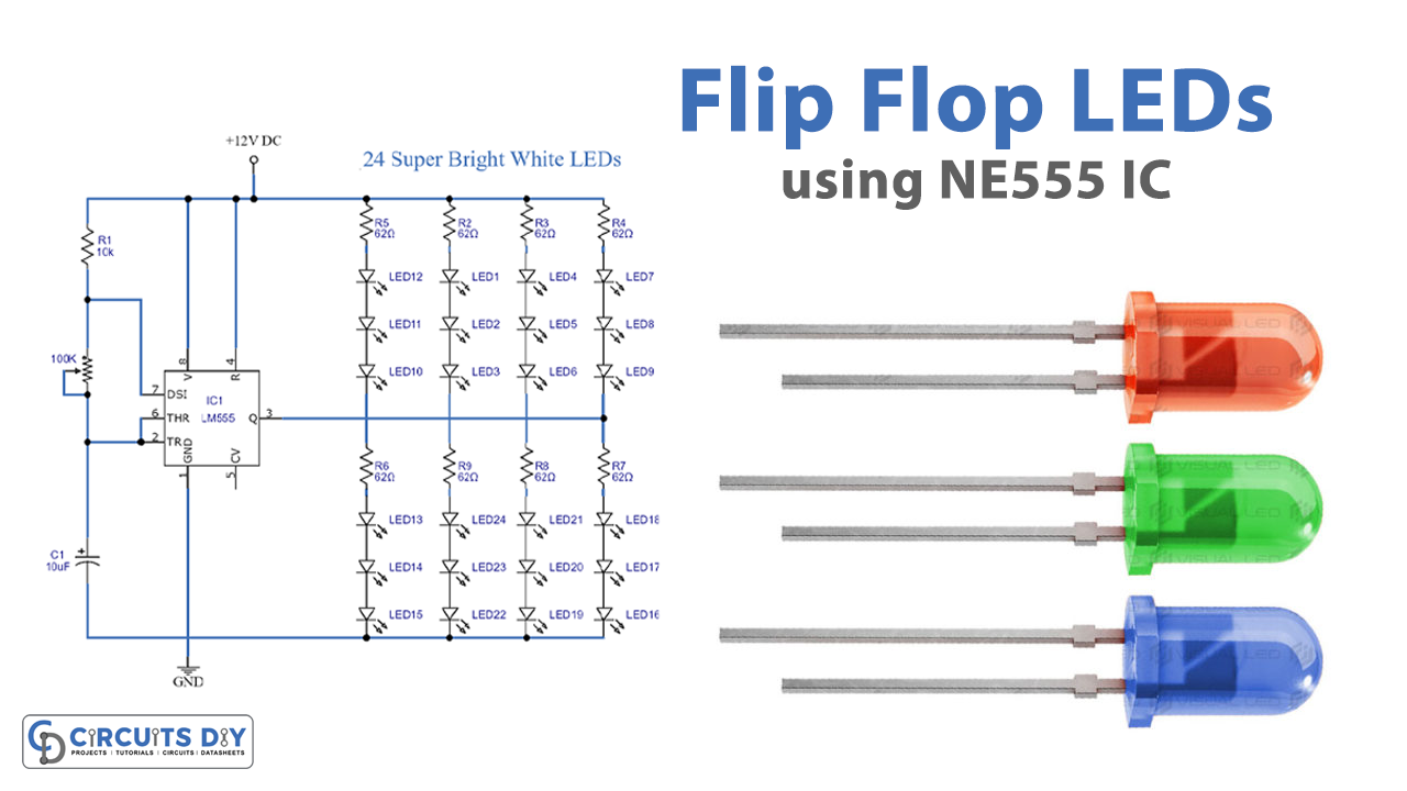
555 flip flop led is a circuit that is used to produce a blinking effect of light. The circuit can enable more than one ultra-bright white LEDs to blink. Your preference is dependent on the number of LEDs, but here we use 24 LEDs divided into two pairs of 12 LEDs each. The circuit is assembled around a known 555 timer IC that is wired in as an astable multivibrator.
Astable indicates performance values should not be stable. Therefore performance fluctuates between high and low. The 555 timer IC will blink one by one or in a flip flop pattern for each pair. The blinking speed of LEDs may increase or decrease by changing the value of a capacitor.

Hardware Components
The following components are required to make 555 Flip Flop LEDs Circuit
| S.no | Components | Value | Qty |
|---|---|---|---|
| 1. | Resistors | 10K, 62 ohms | 1,8 |
| 2. | Potentiometer | 100K | 1 |
| 3. | Capacitor | 10uF | 1 |
| 4. | IC | NE555 Timer | 1 |
| 5. | LEDs | – | 24 |
| 6. | Battery | 12V | 1 |
NE555 IC Pinout

For a detailed description of pinout, dimension features, and specifications download the datasheet of 555 Timer
555 Flip Flop LEDs Circuit
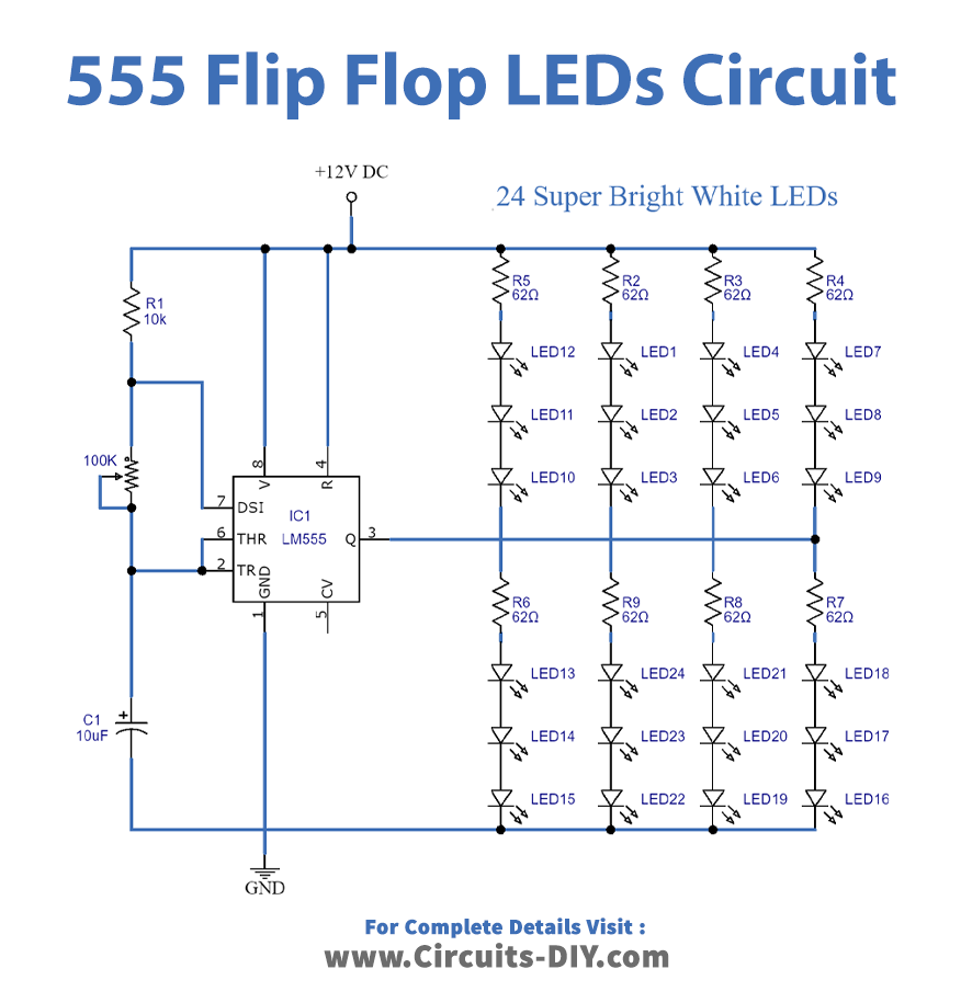
Working Explanation
A 12 volts battery or a power supply is used to run the circuit and for changing the flickering rate per second a 100K potentiometer is used. In-circuit IC NE555 is used that acts as a flip flop or as a multivibrator. This ICs key role is to produce a precise timing pulse. 24 bright white light LEDs are used to produce a flashing effect. A capacitor is used to adjust the light blinking speed of LEDs.
Applications and Uses
One of the implementations for this circuit is fairy lights.