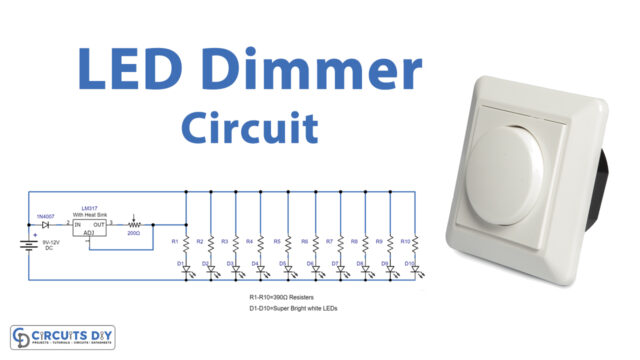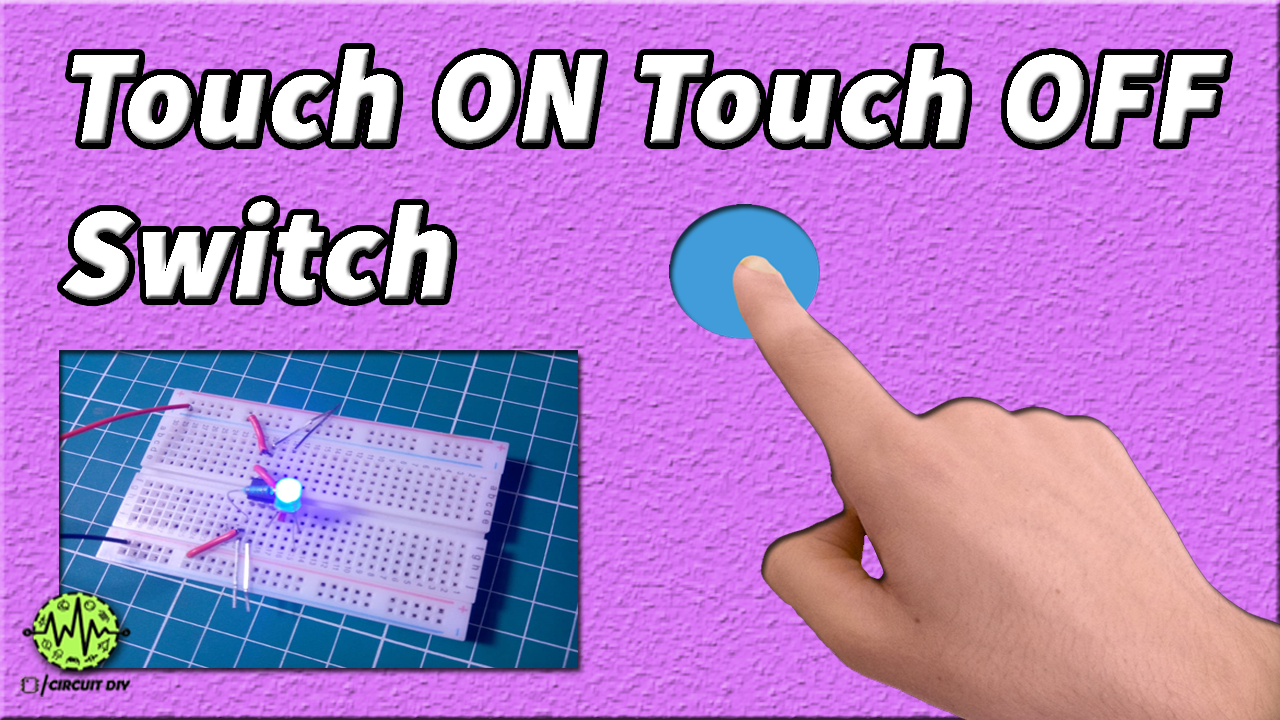
This simple Touch Switch Circuit by using a 555 timer IC operated as a MONOSTABLE vibrator. Here the stable stage is LOW, so the timer outputs low after the trigger is removed. Basically in this circuit, we will have an LED that turns ON when we touch a pin of a timer. The LED will be ON for the time during which the trigger is present. Once the trigger is removed the LED turns OFF.
The main component of this Touch switch circuit is a 555 timer IC. The IC possesses an oscillation frequency ranging from 670 to 680 Hz. Here, this NE555 timer acts as a monostable multivibrator. A monostable multivibrator (MMV) often called a one-shot multivibrator, is a pulse generator circuit in which the duration of the pulse is determined by the R-C network, connected externally to the555 timers. In such a vibrator, one state of output is stable while the other is quasi-stable (unstable). For an auto-triggering output from a quasi-stable state to a stable state, energy is stored by an externally connected capacitor to a reference level. The time taken in storage determines the pulse width.

Hardware Components
The following components are required to make the Touch Switch Circuit
| S. No | Components | Value | Qty |
|---|---|---|---|
| 1. | IC | NE555 Timer | 1 |
| 2. | BreadBoard | – | 1 |
| 3. | Connecting Wires | – | 1 |
| 4. | Battery | 9v | 1 |
| 5. | LED | 5mm | 1 |
| 6. | Resistor | 270 ohms | 1 |
555 Timer Pinout

For a detailed description of pinout, dimension features, and specifications download the datasheet of 555 Timer
Useful Steps
Follow all steps carefully from the video tutorial at the beginning of this post (Highly Recommended).
- STEP # 1 ( Connect IC )
- Connect 555 timer IC on the breadboard
- STEP # 2 ( Make power connections )
- No. 8 Pin of 555 Timer – To VCC of Battery
- Pin 1 of 555 Timer – To GND of Battery
- Pin 6 of 555 Timer – To Pin 2 of 555 Timer
- STEP # 3 ( Connect LED )
- Connect +v LED pin on pin 3 and -ve pin on X-rows of the breadboard
- STEP # 4 ( Connect Resistor )
- Connect 270-ohm resistor BTW pin 1 and -ve terminal of the LED
- STEP # 5 ( Connect metal wire/touch probes )
- connect two metal probes one on pin 8 and the other on pin 6
- connect two more on pin 1 and pin 2
- STEP # 6 ( testing )
Touch Switch Circuit

Working Explanation
In this circuit, the trigger pin in the timer IC is a high-impedance one and is very sensitive. This pin can be triggered just by human body potential. This trigger determines the output of the 555 IC. This trigger pin SETS the flip-flop inside the IC. When this pin is high the output will be high and when this pin is low the output is low.
When the two metallic plates connected across pin 1 & pin 2 come into contact with the human body, the trigger pin forces the internal flip-flop into the SET mode, making the output HIGH. In order to return the IC to RESET mode, the metallic plates between pin 8 & pin 6 are touched in order to return the output to LOW.
Applications
- It is used in many devices such as lamps and wall switches that have a metal exterior as well as on public computer terminals.