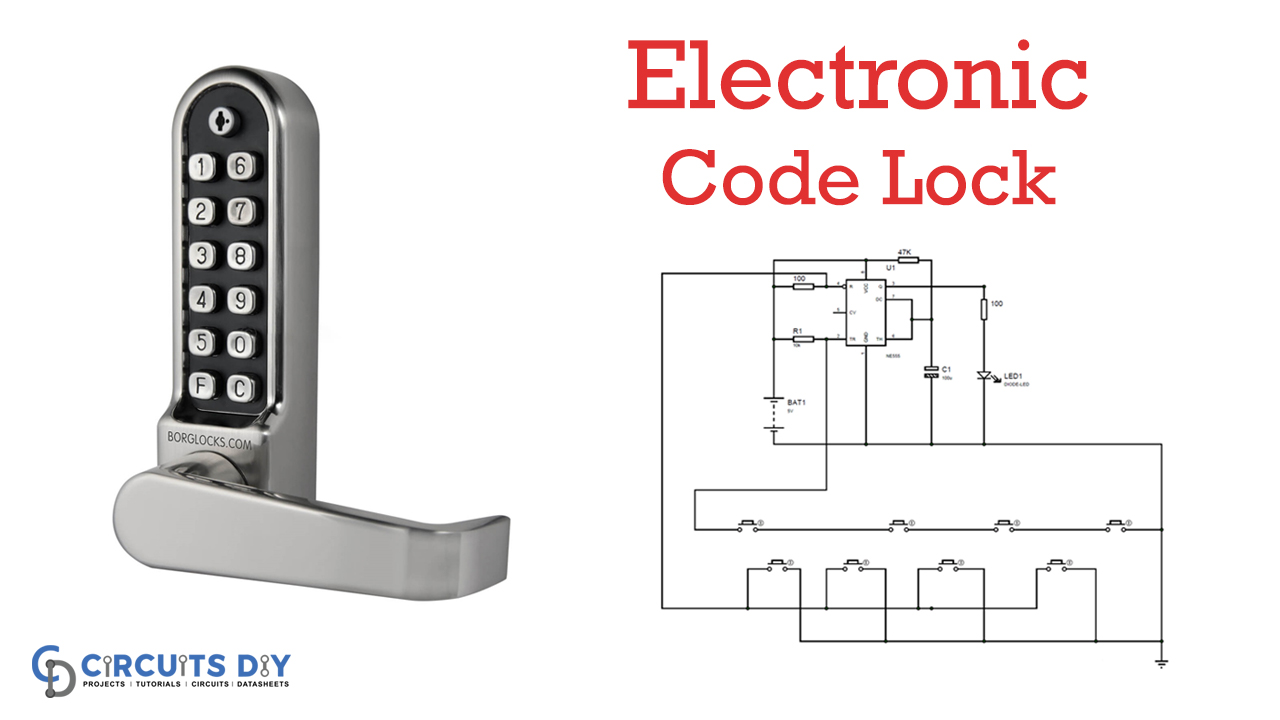
We all know, Digital Code Locks are mainstream in Electronics, where you have to enter a specific ‘Code’ to open the Lock. This sort of lock needs a Microcontroller to contrast the entered code and the predefined code to open the Lock. We have just assembled these sorts of Digital Locks utilizing Arduino, utilizing Raspberry Pi, and utilizing 8051 microcontrollers. Today, we are building the Code Lock by utilizing a 555 Timer IC with no Microcontroller.
In this basic circuit, we are building a 555 Timer IC-based Code Lock. In this Lock, there will be 8 push buttons, and one needs to squeeze a pre-defined four-button all the while to open the Lock. The 555 IC is designed as a Monostable Vibrator here.

Hardware Components
The following components are required to make Electronic Code Lock Circuit
| S.no | Component | Value | Qty |
|---|---|---|---|
| 1. | IC | NE555 Timer | 1 |
| 2. | Resistor | 10K, 47K, 100K, 470 Ohm | 1, 1, 2, 1 |
| 3. | Capacitor | 100uF | 1 |
| 4. | Push Button | – | 8 |
| 5. | LED | – | 1 |
| 6. | Battery | 5V | 1 |
NE555 IC Pinout

For a detailed description of pinout, dimension features, and specifications download the datasheet of 555 Timer
Electronic Code Lock Circuit
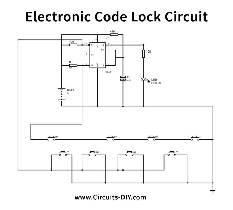
Circuit Operation
As appears in the circuit diagram above, we have a capacitor between PIN6 of 555 timer IC and GROUND. Meanwhile, this capacitor value decides the turning ON season of LED once a trigger is passed. This capacitor can be supplanted with a higher incentive for a more Turning-On period for a solitary trigger. By diminishing the capacitance, we can diminish the Turning-On time after a trigger.
The adjustable voltage applied in the circuit can be any voltage ranging from +3V to +12V, and it must not surpass 12V; doing so will bring about chip harm. The rest of the circuit associations appear in the Circuit Diagram.
Applications and Uses
- Door locks
- Lockers etc.