In this tutorial, we are going to make a “Temperature Controlled DC Fan”.
Sometimes electric fan usage is wasting power. Most people demand something easy to use without wasting energy. And also, most people feel inconvenient about changing the fan speed level mutually when the room temperature change, for their convenience and minimize or reduce power usage, this simple temperature-controlled DC fan circuit is designed with a Negative temperature co-efficient Thermistor and an operational amplifier.
The component that made up the temperature sensor is known as the thermistor when the temperature rises the Thermistor Resistance gets decrease and as the temperature decrease, the Thermistor Resistance gets increases. This Thermistor variable Resistance value is based on the temperature, we can choose the threshold point of temperature by using a variable roll resistor. By this, we can make the electric fan automatically change the speed level according to temperature changes.
Hardware Components
The following components are required to make Temperature Controlled DC Fan Circuit
| S.no | Component | Value | Qty |
|---|---|---|---|
| 1. | Thermistor | 10KΩ | 1 |
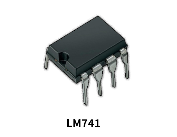
| 2. | Operational Amplifier IC | LM741 | 1 |
| 3. | DC Fan | 9V | 1 |
| 4. | Transistor | BC547 | 1 |
| 5. | Resistor | 4.7KΩ, 39Ω | 1,1 |
| 6. | Variable Resistor | 10KΩ | 1 |
| 7. | Diode | 1N4007 | 1 |
| 8. | Connecting Wires | – | 1 |
| 9. | Power Supply | 9V | 1 |
LM741 Pinout
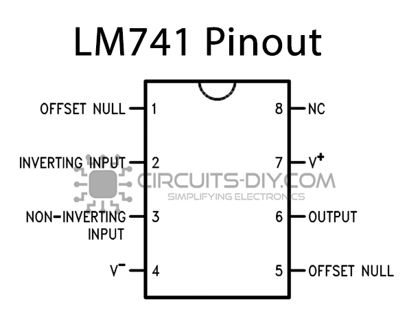
For a detailed description of pinout, dimension features, and specifications download the datasheet of LM741
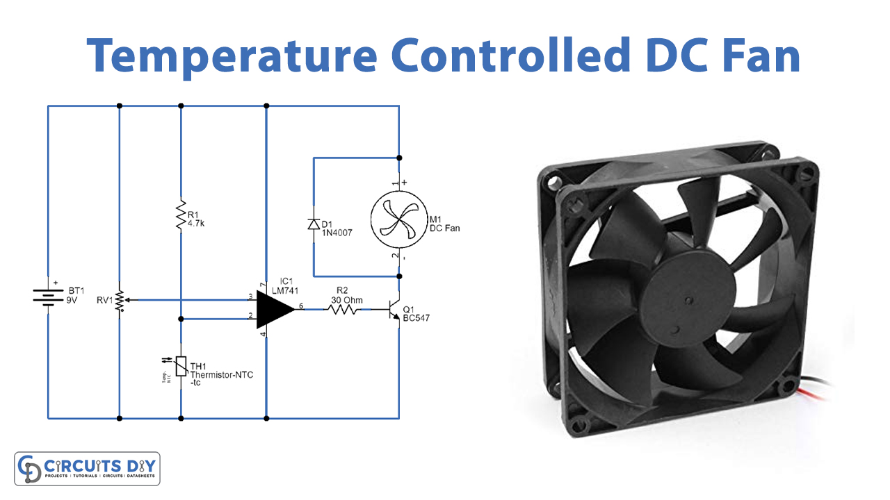
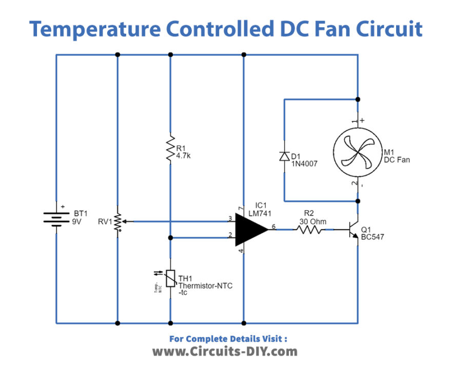
Temperature Controlled DC Fan Circuit
Working Explanation
As shown in the circuit, variable resistor VR1 is connected across the power supply and variable pin is connected to the non-inverting input of IC 741 and then NTC thermistor is connected between the power supply through R1 resistor and also connected with Inverting Input of IC 741. The operational amplifier also uses the same power supply source and the output is connected to the BC547 Q1 transistor base through R2 Resistor. 9V DC fan is conned with positive supply and Q1 transistor collector terminal. The first main component in the circuit is the operational amplifier, which compares reference voltage at the non-inverting input and inverting input and controls the output voltage.
When the temperature increase and reaches the threshold then op-amp gives differential voltage and makes the Q1 transistor turn ON then DC fan gets ground supply and starts to run. If the temperature level is below the threshold, then op-amp gives zero output then Q1 transistor stays in turn OFF condition, and DC fan doesn’t get bias to run and so it remains in off condition. So, the op-amp’s output transistor acts as a switch to connect or disconnect the DC fan from the power supply. We can implement this temperature-controlled DC fan circuit in a common PCB and place the thermistor sensor near the place where temperature control is needed.
Applications
This circuit can be used for simple ventilation and can be connected as a cooling system for rooms, components, and machines needed to reduce or prevent temperature rise.