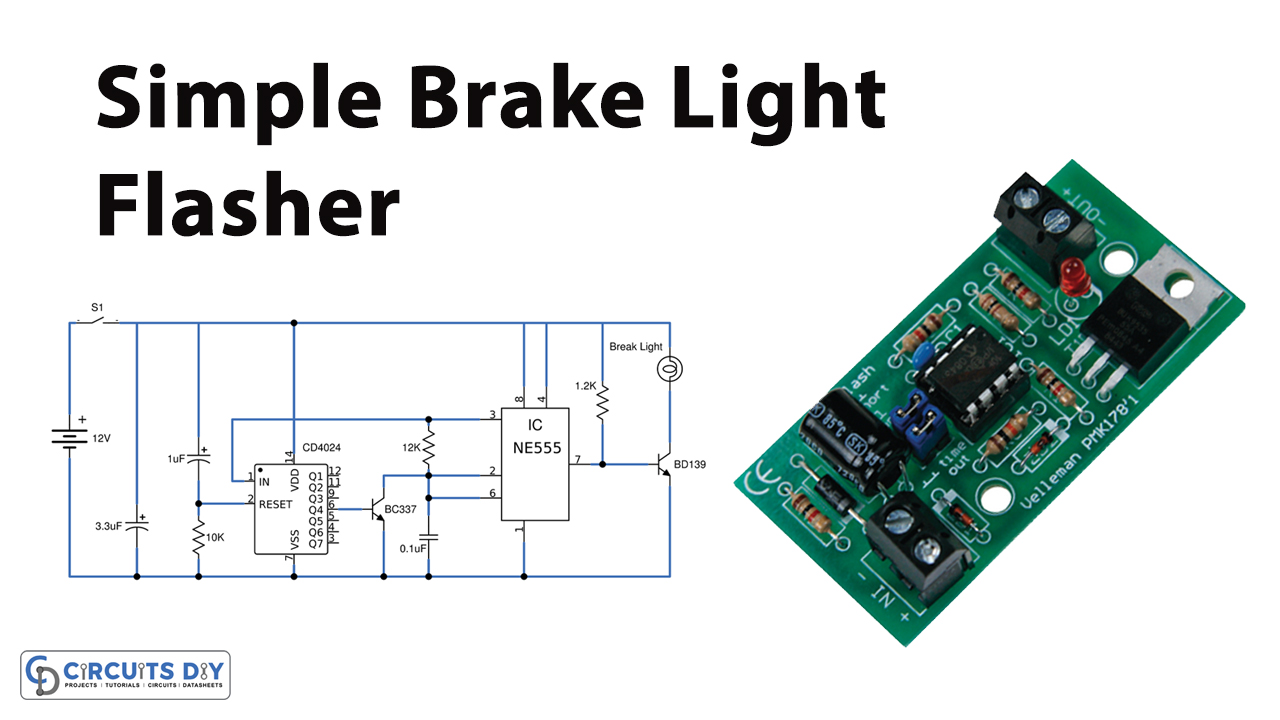
In this tutorial, we are going to make a “Simple Brake light flasher circuit”.
A simple Brake light flasher circuit will flash only when a brake is touched. The rear brake light is a warning light to the behind vehicle, add Caution in tracking. It Can be visible enough far as to add to security than a plain brake light. This flashing light project is installed in automotive vehicles, to modify the brake light. It is easy to build, by using a small number of pieces of equipment, consisting of CMOS IC and power transistors.

Hardware Components
The following components are required to make Brake Light Flasher Circuit
| S.no | Component | Value | Qty |
|---|---|---|---|
| 1. | Resistor | 10K, 1M, 1.2K, | 2,1,1 |
| 2. | Electrolyte Capacitor | 0.1uF, 1uF, 3.3uF | 1,1,1 |
| 3. | Transistor | BC337 | 1 |
| 4. | Transistor | BD139 | 1 |
| 5. | IC | CD4024 | 1 |
| 6. | IC | NE555 timer | 1 |
| 7. | Brake Light | – | 1 |
| 8. | Switch | – | 1 |
| 9. | Supply | 12V | 1 |
| 10. | PCB | – | 1 |
NE555 IC Pinout

For a detailed description of pinout, dimension features, and specifications download the datasheet of NE555 IC
CD4024 Pinout
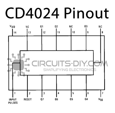
For a detailed description of pinout, dimension features, and specifications download the datasheet of CD4024
Brake Light Flasher Circuit
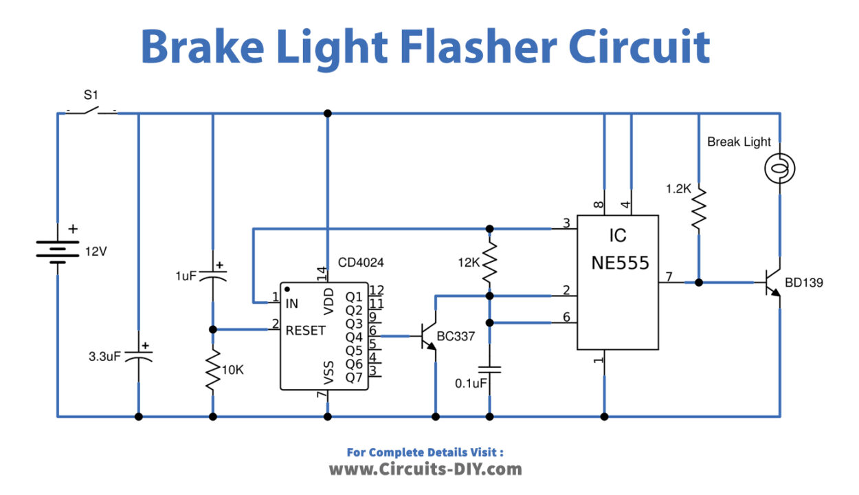
Working Explanations
As shown in the circuit, working starts with power to the circuit or touching the brake. The timer-IC2 gives the drive current to transistors, which will feed a clock signal pulse out to pin3 that goes to pin1 of IC1. It starts counting the amount of pulse and will stop counting when the full 8 pulses obtain. IC1 reset itself by pin2.
The transistor-Q1 is a trigger to IC2 and also results in the reverse stage of pin3 of the IC2. Now because of the voltage drop across R3, IC2 has output voltage at pin7. Due to voltage out at Pin7 transistor-Q2 receiving forward bias signal to drive current, which causes the brake lamp to glow up.
The flashing of the brake light while touching the brake will hold it and flash continuously, as per set around 6 times per second. It defines by the R3 and C3 values. The distance of each series is determined by the C2 and R1. The voltage that feeds to the circuit can use DC 12 volts of Car. The capacitors-C1 is a filter to smooth the currents. The transistors-Q2 may use any number SM3180. We can assemble all components on the universal PCB board.
Applications
This circuit can be used in any vehicle.