Introduction
Maintaining a constant heat source is crucial for the eggs’ survival when it comes to incubators. But what happens when there’s a power outage? Fear not; a 12V backup supply with a battery charger circuit has been designed to save the day!
In this article, we’ll take a closer look at this ingenious circuit that ensures an uninterrupted heat supply for incubator chambers.
The Importance of a Backup Heating System for Incubators
Incubators require a constant heat source to keep the eggs inside at the right temperature for proper hatching. However, power outages can occur unexpectedly, and without a backup heating system, the eggs may not survive. This is where a 12V backup supply with a battery charger circuit comes in handy. The circuit ensures that even if the main power supply is interrupted, the incubator will continue to receive a steady heat supply.
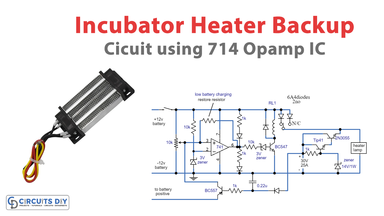
The Design of the Emergency Incubator Lamp with Charger Circuit
The emergency incubator lamp with charger circuit is designed to be simple yet effective. The circuit consists of a Darlington BJT phase, an opamp-based battery overvoltage, and a lower voltage cutoff level. An approximately 14V output is achieved across the emitter of the 2N3005 transistor at a specific current level based on the 1k resistor at the base of the TIP41 transistor. This resistor can be increased or decreased to adjust the emitter current of the 2N3055 correspondingly.
A BC557 transistor is added to address an issue with the circuit. During the charging stage, the battery voltage may be within the full charge and low charge value, which sustains the relay contacts towards the N/C position, reducing the battery voltage from reaching the heater lamp. The BC557 ensures that whenever the mains goes wrong and the relay is at the N/C, it’s forced to revert to the N/O position and hold this until the battery level drops below the fixed risky low voltage level.
Hardware Required
| S no | Components | Value | Qty |
|---|---|---|---|
| 1 | IC | 741 | 1 |
| 2 | Transistor | BC547, BC557, 2N3055, TIP41 | 1, 1, 1, 1 |
| 3 | Resistor | 10k, 1k, | 2, 4 |
| 4 | V. Resistor | 10k | 1 |
| 5 | Non Polar Capacitor | 0.22uF | 1 |
| 6 | Zener Diode | 3V, 14V | 2, 1 |
| 7 | Relay | – | 1 |
| 8 | Diode | 6A4, 1N4148 | 2, 1 |
| 9 | Heater Lamp | – | 1 |
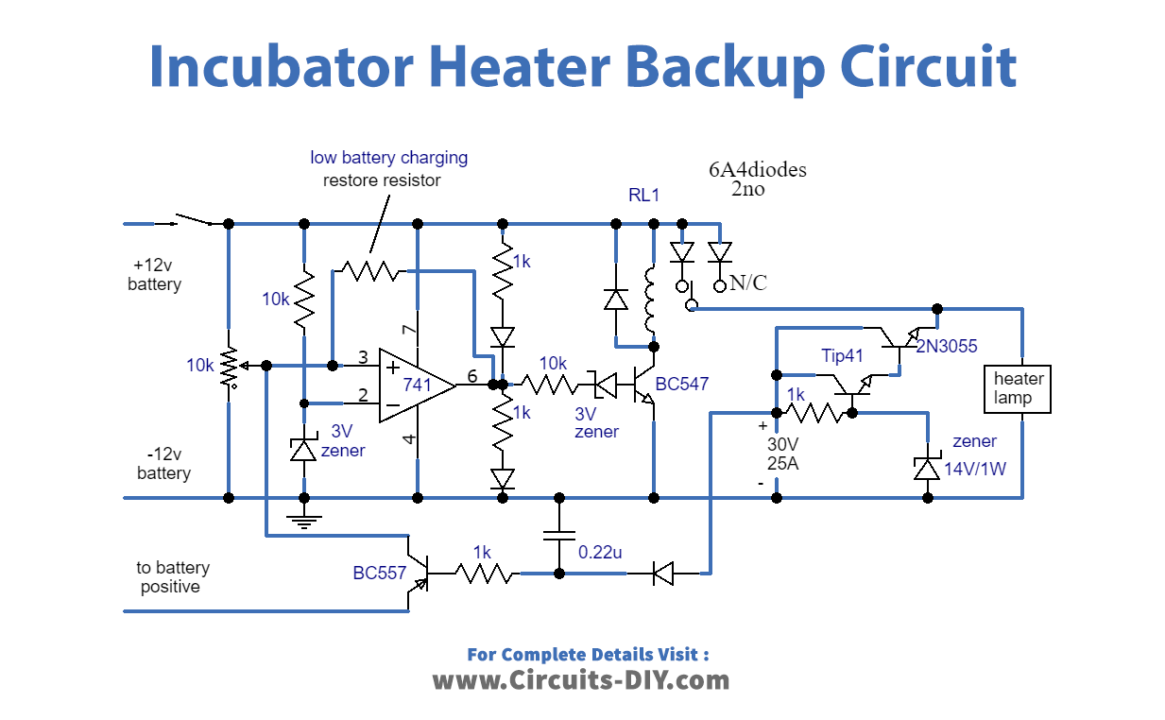
How the 12V Backup Supply Circuit Works for Incubators
Through a battery backup system, the 12V backup supply with a battery charger circuit is designed to provide a continuous heat source to an incubator chamber, regardless of the presence or absence of mains grid voltage. The circuit comprises a transistorized voltage regulator phase created by a Darlington paired 2N3055/TIP41 BJTs, an opamp-based battery overvoltage, and a lower voltage cutoff level. The circuit takes in a 30V input DC from a 30V 25amp transformer after rectifying and filtering it via a bridge rectifier and a 3300uF capacitor.
The controlled output from the circuit powers the incubator heater lamp and charges the connected 12V 60AH battery. As long as the battery voltage is below the optimal full charge level, the red LED stays lit, and the green LED remains off. The relay is also toggled off, allowing the DC voltage from the 2N3055 emitter to flow to the battery through the N/C contact of the relay and the 6amp diode attached at the N/C of the relay.
Once the battery is fully charged, the red LED turns off, the green LED switches on, and the BC547 transistor and the relay. The relay contact switches from N/C to N/O, cutting off the charging supply to the battery and stopping any chance of overcharging. The battery voltage can now reach the heater lamp via the N/O contact, and the series diode at the N/O contact.
Overcoming a Common Issue with the Incubator Heater Backup Circuit
The main issue with the incubator heater backup circuit is that the relay contacts may remain at the N/C position during the charging stage, preventing the battery voltage from reaching the heater lamp. Adding a BC557 transistor ensures that if there is a malfunction in the mains power and the relay is in the N/C position, it will be forced to switch to the N/O position and remain there until the battery level decreases below the predetermined, unsafe minimum voltage threshold.
Final Thoughts
With the 12V backup supply with a battery charger circuit, you can rest assured that your incubator will continue to function even during power outages. Its clever design ensures a steady heat supply to keep your eggs safe and warm. Whether you’re a professional breeder or a hobbyist, this circuit is a must-have for any incubator setup. So go ahead and give it a try – your future chicks will thank you for it!