Introduction
Printed circuit boards are used in almost every electronic device. Hence, it’s a crucial part of electronic circuitry. So, for all electronic students or for those who want to be a circuit designer, it’s preferable to make circuits on printed circuit boards. In short, it’s important to learn the process of designing the PCB. For this purpose, in this article, we will discuss some simple PCB electronic projects that you can make and practice on the PCB. So, to make these projects you can use any PCB software like ORCAD or PROTEL.
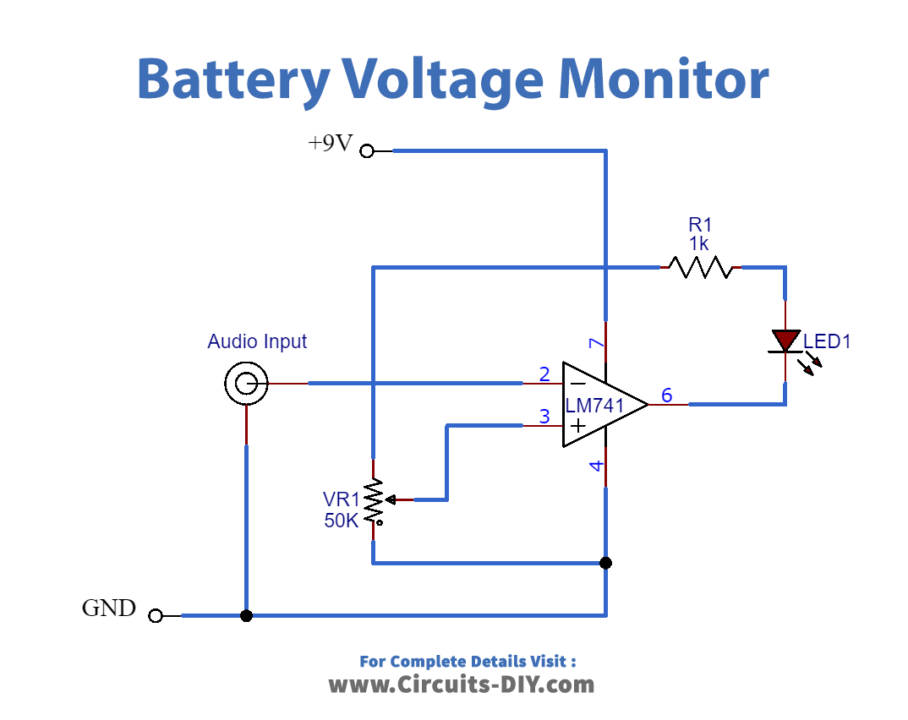
(1) Battery Voltage Monitor
This simple circuit is made from the operational amplifier IC. The IC is operated as a comparator in this circuit. While LED is utilized as an indicator at load. Since this project regulates the discharging and charging of the battery. Therefore, you can make this on PCB and can use it with your battery charger. When the voltage gets rises above, the LED goes low. In the same vein, when the voltage goes low, the LED starts to glow.
Hardware Components
| S.on | Component | Value | Qty |
|---|---|---|---|
| 1. | IC | LM741 | 1 |
| 2. | Variable Resistor | 50k | 1 |
| 3. | LED | – | 1 |
| 4. | Resistor | 1kΩ | 1 |
| 5. | Audio Input | – | 1 |
| 6. | Power Supply | 9V | 1 |
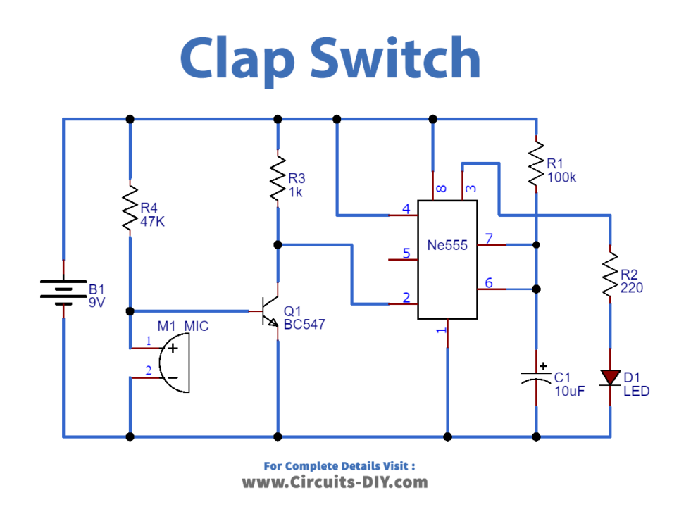
(2) Clap Switch
This very easy project uses the 555 timer IC which works as a monostable multivibrator Its working principle is based on the electronic microphone. When there is a sound, the microphone catches that sound and sends it to the transistors. Transistors amplify those signals and send them to the 555 timer IC. The IC then drives the load accordingly. Make this circuit on a PCB and control your appliances through just one clap.
Hardware Components
| Components | Value | Qty |
|---|---|---|
| NE555 | – | 1 |
| Transistor | BC547 | 1 |
| Capacitor | 10uF | 1 |
| LED | – | 1 |
| Resistor | 220Ω,1K,47,100K | 1,1,1,1 |
| Battery | 9v | 1 |
| Electret MIC | – | 1 |
| Jumper Wires | – | 1 |
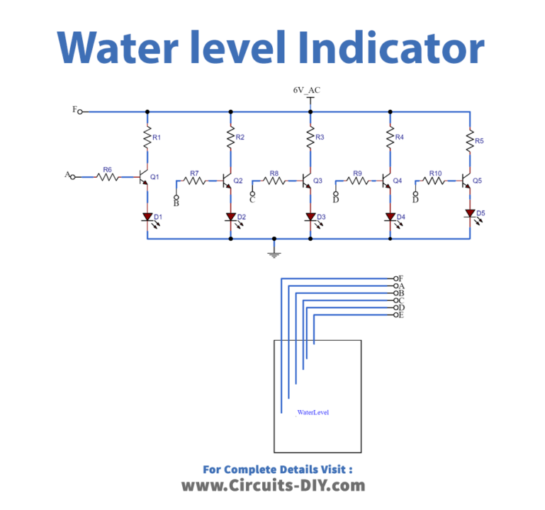
(3) Water level Indicator
The water level indicator is very useful yet easy to make. Practically, used for the measurement of water. The circuit can be made in so many ways using a microcontroller and other programming chips. But, since we aim to provide simple projects that would use fewer components and can be easily assembled on the PCB Board. Therefore, we will use transistors for this project. This three-terminal element is easy to handle on the PCB. So, design this circuit on PCB according to the given schematic. You can also use this project in your home automation system for motors.
Hardware Components
| Components | Value | Qty |
|---|---|---|
| Transistor(T1 to T5) | BC 548 or 2N2222 | 5 |
| LED(D1 to D5) | – | 5 |
| Resistor(R1 to R5) | 2.2K 1/4 W | 5 |
| Resistor (R6 to R10) | 22K 1/4 W | 5 |
| Jumper Wires | – | – |
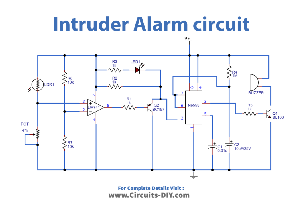
(4) Intruder Alarm circuit
An effective alarm can is used to detect the person. The highly active circuit can also detect the shadow of a person or thing. The central element of a circuit is the photoresistor whose resistance increases or decreases according to the light coming in and going out. When the light befalls on the photoresistor, the resistance gets raised and shows it at the load. Similarly, when the light goes off from the photoresistor, the resistance gets decreased and the circuit load stops working.
Hardware Components
| Components | Value | Qty |
|---|---|---|
| UA741 | – | 1 |
| NE555 | – | 1 |
| Transistor | BC157,SL100 | 1,1 |
| LDR | – | 1 |
| Variable Resistor | 47k | 1 |
| Buzzer | – | 1 |
| Capacitor | 0.01uF,10uF/25V | 1,1 |
| LED | – | 1 |
| Resistor | 1KΩ,10K,1M | 4,2,1 |
| Power Supply | 9V | 1 |
| Jumper Wires | – | 1 |
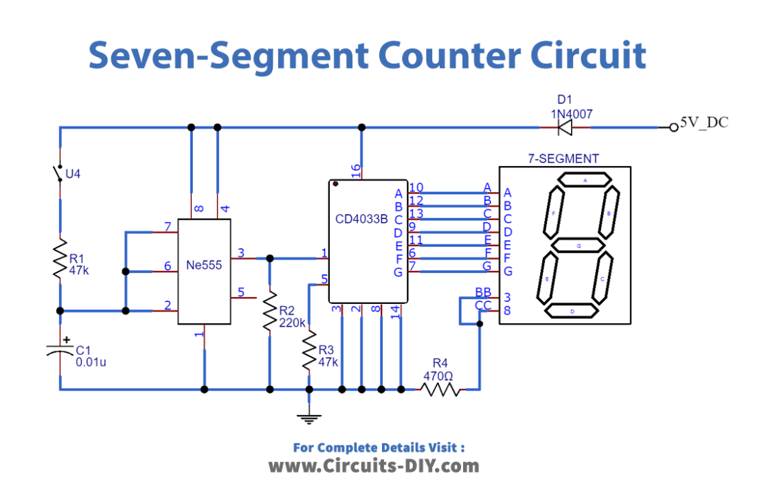
(4) Seven-Segment Counter
A seven-segment counter circuit is an automatic device that counts the numbers. Generally, it counts numbers from 0 to 9 and shows them on the seven-segment device. This circuit essentially uses the seven-segment display which is also popular as a seven-segment indicator. This device is easy to handle on the Printed circuit board The device has seven LEDs. And, Each LED is called the segment and each segment is indicated by the letters from A to G. The circuit also uses the 555 timer IC which works as a monostable multivibrator and produces a single pulse. make this circuit on PCB and wire it with any of your device that needs the counting element.
Hardware Components
| Components | Value | Qty |
|---|---|---|
| CD4033 IC | – | 1 |
| NE555 IC | – | 1 |
| 7-Segment Display | – | 1 |
| Switch | – | 1 |
| Diode | 1N4007 | 1 |
| Resistor | 470Ω,47k,220k | 1,2,1 |
| Capacitor | 0.01uF | 1 |
| Power Supply | 5V-DC | 1 |
| Jumper Wires | – | 1 |
Conclusion
So, we have discussed some basic yet useful and informative circuits that you can easily design on the PCB. Moreover, we have tried to discuss projects that use fewer components. Hence, it would be easy for you to handle it on Printed circuit Boards. Try these amazing projects to step into the design world.